Introductory Circuit Analysis (13th Edition)
13th Edition
ISBN: 9780133923605
Author: Robert L. Boylestad
Publisher: PEARSON
expand_more
expand_more
format_list_bulleted
Concept explainers
Question

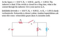
Transcribed Image Text:In the figure ɛ = 10.0 V, R1 = 4.00 N , and R2 = 1.00 N. The
inductor is ideal. If the switch is closed for a long time, what is the
current through the inductor. Give your answer in A.
%3D
10.0 V, R1 = 4.00 N, ve R2 = 1.00 N olarak
Şekildeki devrede ɛ =
verilmişlerdir. Solenoidin iç direnci yoktur. Anahtar kapatıldıktan çok
uzun süre sonra solenoidden geçen akım A cinsinden nedir.
%3|
R
S
R2
E
L
Expert Solution
This question has been solved!
Explore an expertly crafted, step-by-step solution for a thorough understanding of key concepts.
Step by stepSolved in 2 steps with 1 images

Knowledge Booster
Learn more about
Need a deep-dive on the concept behind this application? Look no further. Learn more about this topic, electrical-engineering and related others by exploring similar questions and additional content below.Similar questions
- please answerarrow_forwardFor the circuit in the figurea) Determine the time constant.b) Write the mathematical expression for IL, VL and VR, after the switch is closed.c) Determine IL, VL for one, three and five time constants.d) Draw the waveforms of IL, VL and VR.arrow_forward1. Capacitorsarrow_forward
- Refer to Figure If 50V is applied across the capacitors, determine Q. Write the answer in mC 30 μF 60 µF 20 µF ▬HE HE C₁ C2 C 3 -arrow_forwardSolve for the equivalent inductance at terminals a-b, if L1 = 39 mH and L2 = 98 mH. (Hint: You may add wires and flip the circuitarrow_forwardThe average capacitor discharge current in Figure 252 is a constant Assume a different film capacitor Ex. 252. 9.42 pA for a 0.507 uF film capacitor. C=0.3580 uF results in a different discharge current given by y=-0.08840x + 5.0. Calculate the discharge current (amps) for this different capacitor. If the Arduino was like a 10M Ohm voltmeter, the cap would discharge very quickly. Calculate the time (seconds) to discharge 98.2%, which is four time constants. tau=R*C. ans:2arrow_forward
- HELP plZ IN 10 MINUITSarrow_forwardIn the figure the potential difference V of the battery is 10V. Each capacitor C has a value C = 10 μF. What is the charge on the capacitor C1.arrow_forwardFor the circuit shown in the figure, ϵ0=100Volt, R1=50Ω, R2=100Ω, C=2μF. What is the status of the capacitor immediately after the switch is closed, charged or discharged, and what is the initial current of the battery immediately after the switch is closed?arrow_forward
- Three 20uF capacitors are connected in series with each other. A 1k ohm resistor and an LED connected in series to each other as well, but branched in parallel to all three capacitors. How long would the LED stay lit after power is removed? What current would flow through it during the charge cycle if VT=9v?arrow_forwardFind the Equivalent Capacitance between P and Q from the figure belowarrow_forwardAC Circuits Sine-wave generator f- 25 kHz V₁ = 3.0 V VR 888 100 mH Figure 6-Test Circuit 3. Using a two-channel oscilloscope, measure the peak-to-peak voltage VR across the resistor and the peak-to-peak voltage VL across the inductor. Measure the voltage across the inductor using the difference technique described in a previous experiment. Record the voltage readings in Table 2. VL 10 k 1 XL Table 2- Measured and Calculated Values (f = 25 kHz) ZTarrow_forward
arrow_back_ios
SEE MORE QUESTIONS
arrow_forward_ios
Recommended textbooks for you
 Introductory Circuit Analysis (13th Edition)Electrical EngineeringISBN:9780133923605Author:Robert L. BoylestadPublisher:PEARSON
 Delmar's Standard Textbook Of ElectricityElectrical EngineeringISBN:9781337900348Author:Stephen L. HermanPublisher:Cengage Learning
 Programmable Logic ControllersElectrical EngineeringISBN:9780073373843Author:Frank D. PetruzellaPublisher:McGraw-Hill Education
 Fundamentals of Electric CircuitsElectrical EngineeringISBN:9780078028229Author:Charles K Alexander, Matthew SadikuPublisher:McGraw-Hill Education
 Electric Circuits. (11th Edition)Electrical EngineeringISBN:9780134746968Author:James W. Nilsson, Susan RiedelPublisher:PEARSON
 Engineering ElectromagneticsElectrical EngineeringISBN:9780078028151Author:Hayt, William H. (william Hart), Jr, BUCK, John A.Publisher:Mcgraw-hill Education,

Introductory Circuit Analysis (13th Edition)
Electrical Engineering
ISBN:9780133923605
Author:Robert L. Boylestad
Publisher:PEARSON

Delmar's Standard Textbook Of Electricity
Electrical Engineering
ISBN:9781337900348
Author:Stephen L. Herman
Publisher:Cengage Learning

Programmable Logic Controllers
Electrical Engineering
ISBN:9780073373843
Author:Frank D. Petruzella
Publisher:McGraw-Hill Education

Fundamentals of Electric Circuits
Electrical Engineering
ISBN:9780078028229
Author:Charles K Alexander, Matthew Sadiku
Publisher:McGraw-Hill Education

Electric Circuits. (11th Edition)
Electrical Engineering
ISBN:9780134746968
Author:James W. Nilsson, Susan Riedel
Publisher:PEARSON

Engineering Electromagnetics
Electrical Engineering
ISBN:9780078028151
Author:Hayt, William H. (william Hart), Jr, BUCK, John A.
Publisher:Mcgraw-hill Education,