Electric Motor Control
10th Edition
ISBN: 9781133702818
Author: Herman
Publisher: CENGAGE L
expand_more
expand_more
format_list_bulleted
Concept explainers
Question

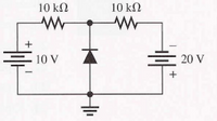
Transcribed Image Text:10 kN
10 kΩ
10 V
E 20 V

Transcribed Image Text:1. Determinewhether each diode in figure 1 is forward biased or reversed biased.
2. Determine the voltage across each diode in figure 1, assuming the practical diode.
Expert Solution
This question has been solved!
Explore an expertly crafted, step-by-step solution for a thorough understanding of key concepts.
Step by stepSolved in 2 steps with 2 images

Knowledge Booster
Learn more about
Need a deep-dive on the concept behind this application? Look no further. Learn more about this topic, electrical-engineering and related others by exploring similar questions and additional content below.Similar questions
- What is the difference between a diode and rectifier?arrow_forward0:- Consider the circuit in Figure a) What type of circuit is this? b) Find and Sketch the voltage waveform across RL, assume the diodes are practical. c) If 100uf capacitor parallel with the resistor, calculate the ripple is connected factor I O o Darrow_forwardExplain th eforward biasing and reverse biasing and how the diodes works?arrow_forward
- I just want to solve the questions at the bottom of the pagearrow_forward1- Connect the Diode Characteristics circuit with a 700 resistor and anvariable AC input voltage source.2- Draw the readings on a V vs I curve and the two graphs look as followsForward bias and reverse bias graph.3- draw the output voltage cross the diode.4- Compare the important features of a silicon versus a germanium diode.arrow_forwardWhat will be the value of the reverse saturation current for a Si diode operating in forward bias mode. The following information is given: Diode current 3 A Voltage across diode 0.25 V. Temperature is 300 K.arrow_forward
- Determine current through each diode in the circuit .Use Practical Diode model. Assume diodes to be similar.arrow_forward1. Determinewhether each diode in figure 1 is forward biased or reversed biased. 2. Determine the voltage across each diode in figure 1, assuming the practical diode.arrow_forwardWhat is Tunnel diode and PIN diode? What are the uses of Tunnel diode and PIN diode? Also draw their symbols.arrow_forward
- In a Schottky diode, the silcon is usually a. un-doped semiconductor b. N-type c. silicon is not used d. P-typearrow_forwardQ1/ +5 V +50 V V R. Vin R 47 N 3.3 kN -5 V -50 V (a) (b) a. Draw the output voltage waveform for each circuit in above figure and include the voltage values. b. What is the peak inverse voltage across each diode? c. What is the peak forward current through each diode?arrow_forward1. Draw the output voltage waveform for each circuit in Figure below and include the voltage values. N +5V +50V Vin R Va R o 0% Y 9 33k 5 Vo -5V -50v I I (@ () a. Whatis the peak inverse voltage across each diode in Figure above? b. What is the peak forward current through each diode in Figure above?arrow_forward
arrow_back_ios
SEE MORE QUESTIONS
arrow_forward_ios
Recommended textbooks for you

 Electricity for Refrigeration, Heating, and Air C...Mechanical EngineeringISBN:9781337399128Author:Russell E. SmithPublisher:Cengage Learning


Electricity for Refrigeration, Heating, and Air C...
Mechanical Engineering
ISBN:9781337399128
Author:Russell E. Smith
Publisher:Cengage Learning