
Introductory Circuit Analysis (13th Edition)
13th Edition
ISBN: 9780133923605
Author: Robert L. Boylestad
Publisher: PEARSON
expand_more
expand_more
format_list_bulleted
Related questions
Concept explainers
Question
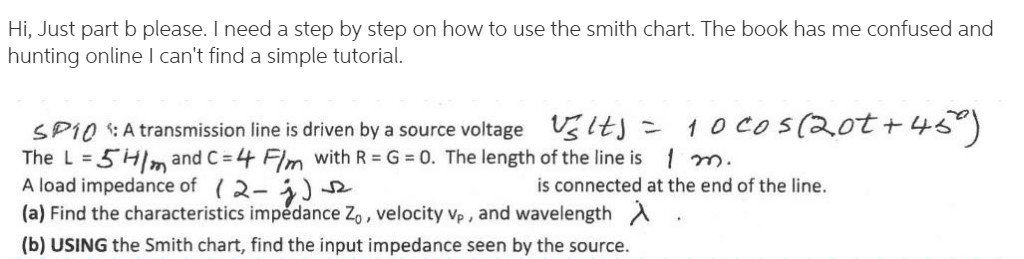

Transcribed Image Text:Hi, Just part b please. I need a step by step on how to use the smith chart. The book has me confused and
hunting online I can't find a simple tutorial.
SP1O :A transmission line is driven by a source voltage Uslts = 1 O Cos(2ot +45)
The L = 5Hm and C = 4 Flm with R = G = 0. The length of the line is 1 m.
A load impedance of (2-)
(a) Find the characteristics impedance Z,, velocity vp , and wavelength A
is connected at the end of the line.
(b) USING the Smith chart, find the input impedance seen by the source.
Expert Solution
This question has been solved!
Explore an expertly crafted, step-by-step solution for a thorough understanding of key concepts.

Step by stepSolved in 2 steps with 2 images

Knowledge Booster


Learn more about
Need a deep-dive on the concept behind this application? Look no further. Learn more about this topic, electrical-engineering and related others by exploring similar questions and additional content below.Similar questions
- I turned the voltage value of the AC source into Vrms and got magnitude 16.97 & angle 10.Then calculated the impedance of Load A to be [ -9.28 - j23.4 ]. From that, I calculated the complex power of load B to be [ -2.42 + j6.33 ] my power factor calculation I am using inverse tan ( Q/P) , where Q i got -1.91 & P to be 5.559, which I got from my total complex power. If that helps. But I am calculating a negative power factor, so i am curious where I went wrong, Thank you!arrow_forwardThe impedance of a transmission line with a length of 50 km is given as z = 0.08 + j0.48 22/km. At the end of the line, a power of 250 MW is drawn with a lagging power factor of cosy = 0.95 under 220 kV voltage. Under these conditions, find the voltage, current, and power factor at the beginning of the line.arrow_forwardQ1: Three-phase composite conductor transmission line is operated at 60 Hz, each conductor has three strands as shown below. Find the total value of inductance in (H/m) and the inductive reactance per phase in (0/mile). O TO Cond, X re03 cm 150 Cond. Y -0.5cm CO diversity d BMW The delivery Xarrow_forward
arrow_back_ios
arrow_forward_ios
Recommended textbooks for you
- Introductory Circuit Analysis (13th Edition)Electrical EngineeringISBN:9780133923605Author:Robert L. BoylestadPublisher:PEARSON
 Delmar's Standard Textbook Of ElectricityElectrical EngineeringISBN:9781337900348Author:Stephen L. HermanPublisher:Cengage Learning
 Programmable Logic ControllersElectrical EngineeringISBN:9780073373843Author:Frank D. PetruzellaPublisher:McGraw-Hill Education
  Fundamentals of Electric CircuitsElectrical EngineeringISBN:9780078028229Author:Charles K Alexander, Matthew SadikuPublisher:McGraw-Hill Education
 Electric Circuits. (11th Edition)Electrical EngineeringISBN:9780134746968Author:James W. Nilsson, Susan RiedelPublisher:PEARSON
 Engineering ElectromagneticsElectrical EngineeringISBN:9780078028151Author:Hayt, William H. (william Hart), Jr, BUCK, John A.Publisher:Mcgraw-hill Education,
Introductory Circuit Analysis (13th Edition)
Electrical Engineering
ISBN:9780133923605
Author:Robert L. Boylestad
Publisher:PEARSON
Delmar's Standard Textbook Of Electricity
Electrical Engineering
ISBN:9781337900348
Author:Stephen L. Herman
Publisher:Cengage Learning
Programmable Logic Controllers
Electrical Engineering
ISBN:9780073373843
Author:Frank D. Petruzella
Publisher:McGraw-Hill Education
Fundamentals of Electric Circuits
Electrical Engineering
ISBN:9780078028229
Author:Charles K Alexander, Matthew Sadiku
Publisher:McGraw-Hill Education
Electric Circuits. (11th Edition)
Electrical Engineering
ISBN:9780134746968
Author:James W. Nilsson, Susan Riedel
Publisher:PEARSON
Engineering Electromagnetics
Electrical Engineering
ISBN:9780078028151
Author:Hayt, William H. (william Hart), Jr, BUCK, John A.
Publisher:Mcgraw-hill Education,