
Introductory Circuit Analysis (13th Edition)
13th Edition
ISBN: 9780133923605
Author: Robert L. Boylestad
Publisher: PEARSON
expand_more
expand_more
format_list_bulleted
Related questions
Question
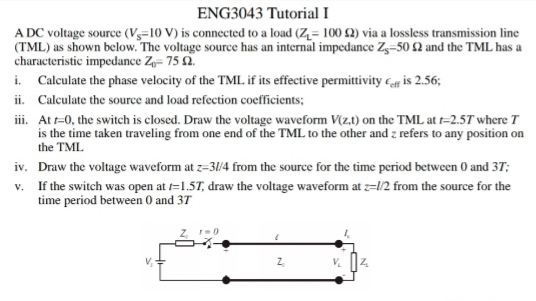

Transcribed Image Text:ENG3043 Tutorial I
A DC voltage source (Vs=10 V) is connected to a load (Z= 100 2) via a lossless transmission line
(TML) as shown below. The voltage source has an internal impedance Zg–50 £2 and the TML has a
characteristic impedance Z- 75 2.
i. Calculate the phase velocity of the TML if its effective permittivity c is 2.56;
ii. Calculate the source and load refection coefficients;
iii. At t-0, the switch is closed. Draw the voltage waveform V(z.1) on the TML at t=2.5T where T
is the time taken traveling from one end of the TML to the other and z refers to any position on
the TML
iv. Draw the voltage waveform at z=3/4 from the source for the time period between 0 and 37;
v. If the switch was open at =1.57, draw the voltage waveform at z=l/2 from the source for the
time period between 0 and 37
Expert Solution
This question has been solved!
Explore an expertly crafted, step-by-step solution for a thorough understanding of key concepts.

Step by stepSolved in 2 steps with 1 images

Knowledge Booster


Learn more about
Need a deep-dive on the concept behind this application? Look no further. Learn more about this topic, electrical-engineering and related others by exploring similar questions and additional content below.Similar questions
- I turned the voltage value of the AC source into Vrms and got magnitude 16.97 & angle 10.Then calculated the impedance of Load A to be [ -9.28 - j23.4 ]. From that, I calculated the complex power of load B to be [ -2.42 + j6.33 ] my power factor calculation I am using inverse tan ( Q/P) , where Q i got -1.91 & P to be 5.559, which I got from my total complex power. If that helps. But I am calculating a negative power factor, so i am curious where I went wrong, Thank you!arrow_forwardThe impedance of a transmission line with a length of 50 km is given as z = 0.08 + j0.48 22/km. At the end of the line, a power of 250 MW is drawn with a lagging power factor of cosy = 0.95 under 220 kV voltage. Under these conditions, find the voltage, current, and power factor at the beginning of the line.arrow_forwardSolve A-Earrow_forward
Recommended textbooks for you
- Introductory Circuit Analysis (13th Edition)Electrical EngineeringISBN:9780133923605Author:Robert L. BoylestadPublisher:PEARSON
 Delmar's Standard Textbook Of ElectricityElectrical EngineeringISBN:9781337900348Author:Stephen L. HermanPublisher:Cengage Learning
 Programmable Logic ControllersElectrical EngineeringISBN:9780073373843Author:Frank D. PetruzellaPublisher:McGraw-Hill Education
  Fundamentals of Electric CircuitsElectrical EngineeringISBN:9780078028229Author:Charles K Alexander, Matthew SadikuPublisher:McGraw-Hill Education
 Electric Circuits. (11th Edition)Electrical EngineeringISBN:9780134746968Author:James W. Nilsson, Susan RiedelPublisher:PEARSON
 Engineering ElectromagneticsElectrical EngineeringISBN:9780078028151Author:Hayt, William H. (william Hart), Jr, BUCK, John A.Publisher:Mcgraw-hill Education,
Introductory Circuit Analysis (13th Edition)
Electrical Engineering
ISBN:9780133923605
Author:Robert L. Boylestad
Publisher:PEARSON
Delmar's Standard Textbook Of Electricity
Electrical Engineering
ISBN:9781337900348
Author:Stephen L. Herman
Publisher:Cengage Learning
Programmable Logic Controllers
Electrical Engineering
ISBN:9780073373843
Author:Frank D. Petruzella
Publisher:McGraw-Hill Education
Fundamentals of Electric Circuits
Electrical Engineering
ISBN:9780078028229
Author:Charles K Alexander, Matthew Sadiku
Publisher:McGraw-Hill Education
Electric Circuits. (11th Edition)
Electrical Engineering
ISBN:9780134746968
Author:James W. Nilsson, Susan Riedel
Publisher:PEARSON
Engineering Electromagnetics
Electrical Engineering
ISBN:9780078028151
Author:Hayt, William H. (william Hart), Jr, BUCK, John A.
Publisher:Mcgraw-hill Education,