Elements Of Electromagnetics
7th Edition
ISBN: 9780190698614
Author: Sadiku, Matthew N. O.
Publisher: Oxford University Press
expand_more
expand_more
format_list_bulleted
Concept explainers
Question
thumb_up100%

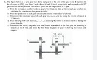
Transcribed Image Text:1. The figure below is a spur gear train drive and gear 2 is the inlet of the gear train. It transfers 12
kw of power at 1200 rpm. Gear 3 and 4 have 60 and 20 teeth respectively and are made with 20°
pressure and full-depth teeth. The desired speed for the output shaft is 32 rpm.
a. Find the minimum number tooth on gear 2 to obtain 32 rpm at the output and confirm its
validation for interference-free power transfer.
b. Find the speed ratio at each gear set using the results obtained at "a"(above).
c. Determine the rotational speed of each gear (n2, n3, n4, and n5) using the results obtained at
"a"(above).
d. Find the torque of each shaft (Tin, Te, Tout) assuming that there is no frictional loss during the
power transfer.
e. Determine the radial, tangential and total forces transmitted at the last gear set assuming a
module as m=4 mm, and draw the free body diagram of gear 4 showing the forces and
torques.
75, 100
2007
In
Out
4
Expert Solution
This question has been solved!
Explore an expertly crafted, step-by-step solution for a thorough understanding of key concepts.
This is a popular solution
Trending nowThis is a popular solution!
Step by stepSolved in 4 steps with 6 images

Knowledge Booster
Learn more about
Need a deep-dive on the concept behind this application? Look no further. Learn more about this topic, mechanical-engineering and related others by exploring similar questions and additional content below.Similar questions
- b) Figure Q1b shows a compound gear train with Gear A as the pinion (or driver) with an input Power (Pin) of 600 W at Gear A. If Gear A rotates at 139.70 rpm and engages with Gear B, calculate the angular velocity (w) in rad/s for Gears B, C & D; and the input torque (Tin) in at Gear A and output torque (Tout) at Gear D. The number of teeth (N) for gears A, B, C & D are 62 teeth, 34 teeth, 42 teeth and 22 teeth, respectively. Assume 100% efficiency and no frictional losses; and give your answers to two decimal places. GEAR A GEAR C GEAR B GEAR Darrow_forwardA gear box has an input speed of 1800 rev/min clockwise and an output speed of 400 rev/min The input power is 25kW and the efficiency is 90%. Compute the input torque the output power 3. the output torquearrow_forwardExplain the following terms with reference to Spur gears: ①Pitch circle ② pressure angle ⑤ Backlash 6 Base Circle 3 circular pitch (4) Addendumarrow_forward
Recommended textbooks for you
 Elements Of ElectromagneticsMechanical EngineeringISBN:9780190698614Author:Sadiku, Matthew N. O.Publisher:Oxford University Press
 Mechanics of Materials (10th Edition)Mechanical EngineeringISBN:9780134319650Author:Russell C. HibbelerPublisher:PEARSON
 Thermodynamics: An Engineering ApproachMechanical EngineeringISBN:9781259822674Author:Yunus A. Cengel Dr., Michael A. BolesPublisher:McGraw-Hill Education
 Control Systems EngineeringMechanical EngineeringISBN:9781118170519Author:Norman S. NisePublisher:WILEY
 Mechanics of Materials (MindTap Course List)Mechanical EngineeringISBN:9781337093347Author:Barry J. Goodno, James M. GerePublisher:Cengage Learning
 Engineering Mechanics: StaticsMechanical EngineeringISBN:9781118807330Author:James L. Meriam, L. G. Kraige, J. N. BoltonPublisher:WILEY

Elements Of Electromagnetics
Mechanical Engineering
ISBN:9780190698614
Author:Sadiku, Matthew N. O.
Publisher:Oxford University Press

Mechanics of Materials (10th Edition)
Mechanical Engineering
ISBN:9780134319650
Author:Russell C. Hibbeler
Publisher:PEARSON

Thermodynamics: An Engineering Approach
Mechanical Engineering
ISBN:9781259822674
Author:Yunus A. Cengel Dr., Michael A. Boles
Publisher:McGraw-Hill Education

Control Systems Engineering
Mechanical Engineering
ISBN:9781118170519
Author:Norman S. Nise
Publisher:WILEY

Mechanics of Materials (MindTap Course List)
Mechanical Engineering
ISBN:9781337093347
Author:Barry J. Goodno, James M. Gere
Publisher:Cengage Learning

Engineering Mechanics: Statics
Mechanical Engineering
ISBN:9781118807330
Author:James L. Meriam, L. G. Kraige, J. N. Bolton
Publisher:WILEY