Delmar's Standard Textbook Of Electricity
7th Edition
ISBN: 9781337900348
Author: Stephen L. Herman
Publisher: Cengage Learning
expand_more
expand_more
format_list_bulleted
Question
please answer all parts of the question and please include a neat sketch of the bode plot and how you got the bode plot values thank you

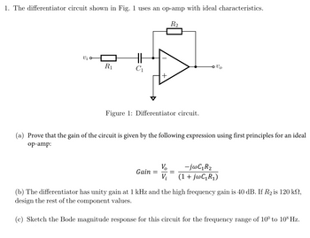
Transcribed Image Text:1. The differentiator circuit shown in Fig. 1 uses an op-amp with ideal characteristics.
R2
Vi σ
R₁
Vo
Figure 1: Differentiator circuit.
(a) Prove that the gain of the circuit is given by the following expression using first principles for an ideal
op-amp:
Vo
Gain =
Vi
-jwC₁R₂
(1 + jwC₁R₁)
(b) The differentiator has unity gain at 1 kHz and the high frequency gain is 40 dB. If R2 is 120 kn,
design the rest of the component values.
(c) Sketch the Bode magnitude response for this circuit for the frequency range of 10° to 108 Hz.
Expert Solution
This question has been solved!
Explore an expertly crafted, step-by-step solution for a thorough understanding of key concepts.
Step by stepSolved in 2 steps with 3 images

Knowledge Booster
Similar questions
- Please show all workarrow_forwardDiscussion: 1- What kind of restrictions Non- inverting op-amp face compared to inverting op-amp? 2- State 5 different types of op amp. Demonstrate them briefly then draw the circuit diagram for each kind. 3- For an inverting op amp, if the voltage input peak equal to 10.2 V, R=10KQ and RF 2002, find Vo and the voltage gain. Assume the input signal has a sinusoidal behavior. 4- Consider an OP amp connected to the inverting configuration to realize a closed-loop gain of -50 V/V utilizing resistors o f 1 k2 and 50 kQ. A load resistance RL is connected from the output to ground, and a low-frequency sine wave signal of peak amplitude Vp is applied to the input. Let the OP amp be ideal except that its output voltage saturates at +/- 10V and its output current is limited to the range +/-15 mA. For RL = 1 k2, what is the maximum possible value of Vp while an undistorted output sinusoid is obtained?arrow_forwardPlease show workarrow_forward
- Answer question belowarrow_forward7. Two important conclusions of an ideal operational amplifier are are ( ). A. Virtual ground and opposite phase B. Virtual short and virtual ground C. Virtual short and virtual open D. Open circuit and short circuitarrow_forwardplease help with both a) and b)..arrow_forward
- This is about OpAmp Circuits. Please make it clear so I can understand, thanks.arrow_forward+15 V V. Ideally, when the two input terminals of an op-amp are shorted together (creating a condition of zerc differential voltage), and those two inputs are connected directly to ground (creating a condition of zero common-mode voltage), what should this op-amp's output voltage be? In reality, the output voltage of an op-amp under these conditions is not the same as what would be ideally predicted. Identify the fundamental problem in real op-amps, and also identify the best solution.arrow_forwardplease solve urgentarrow_forward
- Write (T) for truc or (F) for False for the following: 1. An ideal op-amp has very high input impedance. 2. A differential amplifier is the first stage in all op-amps. 3 If the same voltage applied to both inputs of op-amp, the mode of operation is called double-ended mode .4 A practical op-amp has non-zero output impedance. 5. In zero level detector. the output changes state when the input becomes negative. 6. An averaging amplifier with 10 inputs has the ratio of R/ R isarrow_forwardDetermine the CMRR and express it in dB for an op-amp with an open-loop differential voltage gain of 85,000 and a common-mode gain of 0.25. When a pulse is applied to an op-amp, the output voltage goes from -8 V to +7 V in 0.75 µs. What is the slew rate? Differentiate the working principle of differential and operational amplifier and its operation. Discuss your answer in at least 5 sentences.arrow_forwardAn op-amp has a unity-gain frequency (funity) of 12MHz. What is the amplifier's bandwidth, in kHz, when ACL = 536?arrow_forward
arrow_back_ios
SEE MORE QUESTIONS
arrow_forward_ios
Recommended textbooks for you
 Delmar's Standard Textbook Of ElectricityElectrical EngineeringISBN:9781337900348Author:Stephen L. HermanPublisher:Cengage Learning

Delmar's Standard Textbook Of Electricity
Electrical Engineering
ISBN:9781337900348
Author:Stephen L. Herman
Publisher:Cengage Learning