Introduction to Chemical Engineering Thermodynamics
8th Edition
ISBN: 9781259696527
Author: J.M. Smith Termodinamica en ingenieria quimica, Hendrick C Van Ness, Michael Abbott, Mark Swihart
Publisher: McGraw-Hill Education
expand_more
expand_more
format_list_bulleted
Question
ANSWERS FOUND IN RED WRITING PLEASE SHOW WORKING ON HOW TO REACH THESE
![1. [Flow equalisation, effect of equalisation on BOD mass loading rate]. Consider the volumetric
flowrates and BOD concentrations given in the following table:
Time period
midnight-1am
1am-2am
2am-3am
3am-4am
4am-5am
5am-6am
6am-7am
7am-8am
8am-9am
9am-10am
10am-11am
11am-12
12-1pm
1pm-2pm
2pm-3pm
3pm-4pm
4pm-5pm
5pm-6pm
6pm-7pm
7pm-8pm
8pm-9pm
9pm-10pm
10pm-11pm
11pm-midnight
Average flowrate during Average BOD concentration
time period (m³/s)
during time period (mg/L)
0.275
0.220
0.165
0.130
0.105
0.100
0.120
0.205
0.355
0.410
0.425
0.430
0.425
0.405
0.385
0.350
0.325
0.325
0.330
0.365
0.400
0.400
0.380
0.345
150
115
75
50
45
60
90
130
175
200
215
220
220
210
200
190
180
170
175
210
280
305
245
180
a) Calculate the equalised average flowrate for the day (flowrate fed to downstream processes).
[Ans: 0.307 m³/s = 1105.2 m³/hr]
b) Using the graphical method, (use spreadsheet and/or graph paper), calculate the inline
storage volume required to equalise the flow rate (flowrate equalisation volume)
[Ans: 4110 m³]
c) Determine the dampening effect of flow equalisation on BOD mass loading.
Assume perfect mixing in the equalisation basin/tank
For step-by-step guidance for part (b) and (c): (see back sheet)
Problem text, table, and step-by step guidance adapted/taken from "Example 3-10, pages 245-250,
Metcalf and Eddy, Wastewater Engineering, Treatment and Resource Recovery, 5th ed, vol 1, 2014"](https://content.bartleby.com/qna-images/question/e25ad2c4-6e03-4d3e-b445-5962fa3ab3d6/ca2bd2fb-29d6-406e-a518-60be7404ff21/cgjk1ti_thumbnail.png)
Transcribed Image Text:1. [Flow equalisation, effect of equalisation on BOD mass loading rate]. Consider the volumetric
flowrates and BOD concentrations given in the following table:
Time period
midnight-1am
1am-2am
2am-3am
3am-4am
4am-5am
5am-6am
6am-7am
7am-8am
8am-9am
9am-10am
10am-11am
11am-12
12-1pm
1pm-2pm
2pm-3pm
3pm-4pm
4pm-5pm
5pm-6pm
6pm-7pm
7pm-8pm
8pm-9pm
9pm-10pm
10pm-11pm
11pm-midnight
Average flowrate during Average BOD concentration
time period (m³/s)
during time period (mg/L)
0.275
0.220
0.165
0.130
0.105
0.100
0.120
0.205
0.355
0.410
0.425
0.430
0.425
0.405
0.385
0.350
0.325
0.325
0.330
0.365
0.400
0.400
0.380
0.345
150
115
75
50
45
60
90
130
175
200
215
220
220
210
200
190
180
170
175
210
280
305
245
180
a) Calculate the equalised average flowrate for the day (flowrate fed to downstream processes).
[Ans: 0.307 m³/s = 1105.2 m³/hr]
b) Using the graphical method, (use spreadsheet and/or graph paper), calculate the inline
storage volume required to equalise the flow rate (flowrate equalisation volume)
[Ans: 4110 m³]
c) Determine the dampening effect of flow equalisation on BOD mass loading.
Assume perfect mixing in the equalisation basin/tank
For step-by-step guidance for part (b) and (c): (see back sheet)
Problem text, table, and step-by step guidance adapted/taken from "Example 3-10, pages 245-250,
Metcalf and Eddy, Wastewater Engineering, Treatment and Resource Recovery, 5th ed, vol 1, 2014"

Transcribed Image Text:1.b)
• Step 1
The first step is to develop a cumulative volume curve of the wastewater flowrate expressed in
cubic meters. The cumulative curve is obtained by summing the hourly values to obtain a
cumulative volume curve.
Tutorial 4-Step-by-Step guidance
Step 2
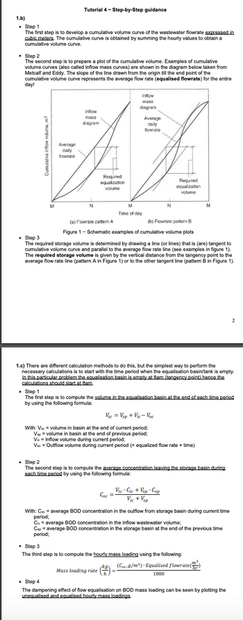
The second step is to prepare a plot of the cumulative volume. Examples of cumulative
volume curves (also called inflow mass curves) are shown in the diagram below taken from
Metcalf and Eddy. The slope of the line drawn from the origin till the end point of the
cumulative volume curve represents the average flow rate (equalised flowrate) for the entire
day!
M
Average
daily
flowrate
Inflow
mass
diagram
N
Required
equalization
volume
Inflow
mass
diagram
M
Time of day
Average
daily
flowrate
N
Сос
Required
equalization
volume
(a) Flowrate pattern A
(b) Flowrate pattern B
Figure 1 - Schematic examples of cumulative volume plots
. Step 3
The required storage volume is determined by drawing a line (or lines) that is (are) tangent to
cumulative volume curve and parallel to the average flow rate line (see examples in figure 1).
The required storage volume is given by the vertical distance from the tangency point to the
average flow rate line (pattern A in Figure 1) or to the other tangent line (pattern B in Figure 1).
1.c) There are different calculation methods to do this, but the simplest way to perform the
necessary calculations is to start with the time period when the equalisation basin/tank is empty.
In this particular problem the equalisation basin is empty at 8am (tangency point) hence the
calculations should start at 8am.
Vsc = Vsp + Vic-Voc
With: Vsc = volume in basin at the end of current period;
Vsp = volume in basin at the end of previous period;
Vie Inflow volume during current period;
Voc = Outflow volume during current period (= equalized flow rate x time)
• Step 1
The first step is to compute the volume in the equalisation basin at the end of each time period
by using the following formula:
Vic. Cic+Vsp Csp
= Vic+Vsp
M
. Step 2
The second step is to compute the average concentration leaving the storage basin during
each time period by using the following formula:
With: Coc = average BOD concentration in the outflow from storage basin during current time
period;
Cic= average BOD concentration in the inflow wastewater volume;
Csp = average BOD concentration in the storage basin at the end of the previous time
period;
. Step 3
The third step is to compute the hourly mass loading using the following:
jkg. (Coc. 9/m³). Equalised flowrate (
Mass loading rate (=
1000
2
• Step 4
The dampening effect of flow equalisation on BOD mass loading can be seen by plotting the
unequalised and equalised hourly mass loadings.
Expert Solution
This question has been solved!
Explore an expertly crafted, step-by-step solution for a thorough understanding of key concepts.
Step 1: Given
VIEW Step 2: (a) Calculate the equalized average flowrate for the day
VIEW Step 3: (b) Calculate the inline storage volume required to equalize the flow rate
VIEW Step 4: (c)Determine the dampening effect of flow equalization on BOD mass loading
VIEW Step 5: Calculation continue
VIEW Step 6: Calculation continue
VIEW Solution
VIEW Step by stepSolved in 7 steps with 26 images

Knowledge Booster
Similar questions
- Where do you get C=p/M?arrow_forwardsir do you have a graph or diagram for this please??arrow_forwardWearing slippers, shorts, and sleeveless shirts are not allowed inside the laboratory * at all times if and only if the instructor fails to check the proper PPE of each student before an experiment when a student does not have their hand gloves and goggles on when a student does not feel like wearing themarrow_forward
- True or false. if the statement is FALSE, place the correct word/s that should replace the word/s in capital letters to make the statement true.arrow_forwardthis is amazing, can you expand a litte more on how to create this in excelarrow_forwarda) Identify the process industries in Oman where these mass transfer operations aredeployed and discuss their uses in process industry.arrow_forward
arrow_back_ios
SEE MORE QUESTIONS
arrow_forward_ios
Recommended textbooks for you
 Introduction to Chemical Engineering Thermodynami...Chemical EngineeringISBN:9781259696527Author:J.M. Smith Termodinamica en ingenieria quimica, Hendrick C Van Ness, Michael Abbott, Mark SwihartPublisher:McGraw-Hill Education
 Elementary Principles of Chemical Processes, Bind...Chemical EngineeringISBN:9781118431221Author:Richard M. Felder, Ronald W. Rousseau, Lisa G. BullardPublisher:WILEY
 Elements of Chemical Reaction Engineering (5th Ed...Chemical EngineeringISBN:9780133887518Author:H. Scott FoglerPublisher:Prentice Hall
 Industrial Plastics: Theory and ApplicationsChemical EngineeringISBN:9781285061238Author:Lokensgard, ErikPublisher:Delmar Cengage Learning
 Unit Operations of Chemical EngineeringChemical EngineeringISBN:9780072848236Author:Warren McCabe, Julian C. Smith, Peter HarriottPublisher:McGraw-Hill Companies, The

Introduction to Chemical Engineering Thermodynami...
Chemical Engineering
ISBN:9781259696527
Author:J.M. Smith Termodinamica en ingenieria quimica, Hendrick C Van Ness, Michael Abbott, Mark Swihart
Publisher:McGraw-Hill Education

Elementary Principles of Chemical Processes, Bind...
Chemical Engineering
ISBN:9781118431221
Author:Richard M. Felder, Ronald W. Rousseau, Lisa G. Bullard
Publisher:WILEY

Elements of Chemical Reaction Engineering (5th Ed...
Chemical Engineering
ISBN:9780133887518
Author:H. Scott Fogler
Publisher:Prentice Hall


Industrial Plastics: Theory and Applications
Chemical Engineering
ISBN:9781285061238
Author:Lokensgard, Erik
Publisher:Delmar Cengage Learning

Unit Operations of Chemical Engineering
Chemical Engineering
ISBN:9780072848236
Author:Warren McCabe, Julian C. Smith, Peter Harriott
Publisher:McGraw-Hill Companies, The