
Structural Analysis
6th Edition
ISBN: 9781337630931
Author: KASSIMALI, Aslam.
Publisher: Cengage,
expand_more
expand_more
format_list_bulleted
Related questions
Concept explainers
Question
Determine the slope and deflection at point B of the beam ABC shown using the AreaMoment Method. Use E = 200 GPa and I = 1665 x 106 mm4
SUBJECT: THEORY OF STRUCTURES
THE SECOND PIC IS MY PROGRESS
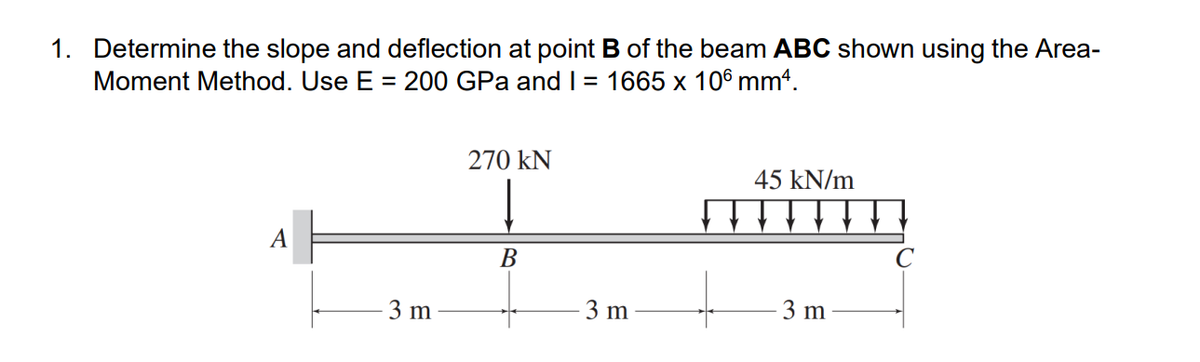

Transcribed Image Text:1. Determine the slope and deflection at point B of the beam ABC shown using the Area-
Moment Method. Use E = 200 GPa and I = 1665 x 106 mm².
270 KN
45 kN/m
A
B
3 m
3 m
3 m
T

Transcribed Image Text:MAA
270 KN
3mm
3m
MEI ALLY
M/E!
wrt pt (Ⓡ
45 kN/m pick ref. point
B
M/2l wrt
pt.
3m
(2) Solve for reactions
ZMA=0;
(3)
14- = 270 (0) = 45 (4+ 2) = 0
MAZ
27 M4 - 270 (3)-45 (3) (6+2) = 0
ма
MA =
= + 1822.30 KN-m, (
4ZFY = 0;
AY-270-45(3) = 0
+ZFx = 0;
✓ An=2°
✓Xn=2°
45 kN/m
-MA = "1822 50 KM²m
#1
PL = 405 (3) - 1215 14-47
E
El
0
-45 (6²) ₂-810 IN-M
EI
2E1
45 (3²)
221
O
202-5 KN.M
E1
=
=
Ay = 4015 KN, 1
Ax = 0
·bh
(2)+1
(2) +z = b
+2
MA
L=3
L=3
B
PL
45kN/m
-Ama LEGM
L=3m
w=95 KNYM
Expert Solution
This question has been solved!
Explore an expertly crafted, step-by-step solution for a thorough understanding of key concepts.

Step by stepSolved in 3 steps with 3 images

Knowledge Booster


Learn more about
Need a deep-dive on the concept behind this application? Look no further. Learn more about this topic, civil-engineering and related others by exploring similar questions and additional content below.Similar questions
- please determine deflection at point C by assuming the stiffness (E,I) is constant (use conjugate beam method)arrow_forwardThe cantilevered handle shown here is made from mild steel. Let Fy= 300 Ibf and Fx= Fz= 0. The part dimensions are as follows: doA = 1.5 in, dAB= 0.875 in and dBc= 1.5 in, dcD=1 in, LAB=10 in, LCD= 12 in. Determine the angle of twist in the bar OC, ignoring the fillets but including the changes in diameter between O and C. Compare the angle of twist if the bar OC is simplified to be of uniform diameter equal to dAB. Use superposition to determine the vertical deflection (along the y-axis) at D, using the simplified bar OC. 2 in A LAB doa B C -in R. 2 in daB dBc dco Lcoarrow_forwardThe maximum deflection for the cantilever-beam below is no more than 0.03m.Macaulay’s method of double integration should be used to determine the second moment of area of the beam cross-section (I) (Please let's the final unit be in mm^4 and also provide a final check) E = 200 GN/m2 Hopefully my sketch is readable! I need a step by step guide with calculations (Readable) pleasearrow_forward
- 2. P Derive an equation that describes the vertical deflection of the beam, y(x), and also B calculate the maximum deflection of the beam. M = 0.5PL %3Darrow_forward1. Use the conjugate-beam method to determine the slope and deflection at point B of the beams shown in the figure. A 2 k/ft -30 ft- El = constant E = 29,000 ksi I = 3,000 in.4 Barrow_forwardProblem 3 Conjugate Beam Method: For the given beam below, answer the questions. El = constant: P M=Pa B a a (a) Draw the conjugate beam (clearly show the supports of the conjugate beam and mark the important values). (b) Determine the slope angle at point B, 0B, of the real beam using the conjugate beam method. Determine the deflection at point B, Ag, of the real beam using the conjugate beam method.arrow_forward
- Find: Using the Principle of Virtual Work, calculate the vertical deflection of Point E, and the horizontal deflection of Point F for the truss shown. Assume E = 10,000 ksi and the following cross-sectional areas: Parts AB, BD, DF, and FH have A=4.0 in? while all other parts have A=1,5 in?. Summarize the results of your calculations in a table so that it is easy to review (similar to calculations shown in class example). 5 kip B F 14 ft E G H 30 kip 10 ft 10 ft 10 ft 10 ftarrow_forwardThe maximum deflection for the cantilever-beam below is no more than 0.03m.Macaulay’s method of double integration should be used to determine the second moment of area of the beam cross-section (I) (Please let's the final unit be in mm^4 and also provide a final check)E = 200 GN/m2 can someone please answer this question in detail who is confident in this topic with step-by-step calculations pls. I've asked this question twice now and I've gotten different answers each time so I'm at a bit of a loss. (Pls don't respond to this if you have already responded previously) Thank youarrow_forward2. Use the virtual work method to determine the horizontal deflections at joint C of the frame shown. 20 kN B B 3 kN/m olish br 10 m H C 10 m El= constant E = 200 GPa 1=400(106) mm²arrow_forward
arrow_back_ios
arrow_forward_ios
Recommended textbooks for you
 Structural Analysis (10th Edition)Civil EngineeringISBN:9780134610672Author:Russell C. HibbelerPublisher:PEARSON
 Principles of Foundation Engineering (MindTap Cou...Civil EngineeringISBN:9781337705028Author:Braja M. Das, Nagaratnam SivakuganPublisher:Cengage Learning
 Fundamentals of Structural AnalysisCivil EngineeringISBN:9780073398006Author:Kenneth M. Leet Emeritus, Chia-Ming Uang, Joel LanningPublisher:McGraw-Hill Education
 Traffic and Highway EngineeringCivil EngineeringISBN:9781305156241Author:Garber, Nicholas J.Publisher:Cengage Learning
Structural Analysis (10th Edition)
Civil Engineering
ISBN:9780134610672
Author:Russell C. Hibbeler
Publisher:PEARSON
Principles of Foundation Engineering (MindTap Cou...
Civil Engineering
ISBN:9781337705028
Author:Braja M. Das, Nagaratnam Sivakugan
Publisher:Cengage Learning
Fundamentals of Structural Analysis
Civil Engineering
ISBN:9780073398006
Author:Kenneth M. Leet Emeritus, Chia-Ming Uang, Joel Lanning
Publisher:McGraw-Hill Education
Traffic and Highway Engineering
Civil Engineering
ISBN:9781305156241
Author:Garber, Nicholas J.
Publisher:Cengage Learning