Introductory Circuit Analysis (13th Edition)
13th Edition
ISBN: 9780133923605
Author: Robert L. Boylestad
Publisher: PEARSON
expand_more
expand_more
format_list_bulleted
Question

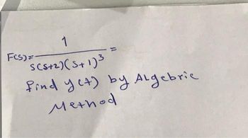
Transcribed Image Text:1
SCS+2)(5+1)³
FCS)=-
find yet) by Algebric.
Method
Expert Solution
This question has been solved!
Explore an expertly crafted, step-by-step solution for a thorough understanding of key concepts.
Step by stepSolved in 2 steps with 1 images

Knowledge Booster
Learn more about
Need a deep-dive on the concept behind this application? Look no further. Learn more about this topic, electrical-engineering and related others by exploring similar questions and additional content below.Similar questions
- Q1. a. A thyristor is used in a d.c circuit and protected by a 50µH inductor and 0.1µF capacitor. Determine the thyristor dv/dt and di/dt rating if the operating voltage of the circuit is 200V and the load resistance is 202. b. Why it is significant to know the diode or thyristor Peak Inverse Voltage (PIV)? 200varrow_forwardneed help with carrow_forwardPt A 6v battery, delivrers lomA to three resistors in paralkel, R, 21kr, R2=2K2,R3%3DRX. Calculate: a) Current in b) Power dissipatid by Rx and R,-[Anss 6mw,36mm. C) Resistance ratio Rx/R--(Ans: 615). ) Cnrrent ratio It/Ix Ans: 6/]. Rx sthat is In-[Anss I mA)-arrow_forward
- VR R a.1 For the Zener diode network shown in the figure to the right, determine VL, VR, Iz, and Pz. 1k2 V2 = 10 V 7 RL1.2 k2 VL 16 V a.2. Repeat part (a.1) with RL = 3 k2. PZM = 30 mW %3Darrow_forwardYou are to design a simple power supply made up of recycled electrical parts to drive a motor. To simplify the design, you can model the running motor as a load resistor. The motor is rated for 20V and draws 100mA when running. 120Vrms Resistor 60HZ Vp Vs 0° + C1 1250pF a = 3.75 Zener "Motor BR805D а. If you were to model the running motor as a resistor what would the resistor value be? b. The transformer has a turns ratio a = 3.75. What are the RMS and Peak values of the secondary voltage? What is the peak voltage after the diode rectifier bridge (without C1, Zener, resistor, or load)? Draw the waveform. d. Determine the ripple voltage (VRIPPLE) without the Zener diode in the circuit (assume the Resistor above is 1002). Determine the part number of a suitable Zener diode to provide an output voltage of approximately 20v. (i.e. 1N4 C. е. 2.arrow_forwarda " zain IQ 45.PNG > Example 33: A thyristor used in a half wave rectifier used 220V. with firing angle 60° , total resistance load 1N , inductance 5mH and frequency 60HZ, calculate: (a) load voltage and current (b) maximum direct voltage and current (c) normalized voltage and current (d) root mean square voltage and current and (f) power factor.arrow_forward
- Rz ww- I2 Ri It For the circuit above, assume D, and D, are Ideal diodes. Circuit elements are given as; V1= 3 Volts V2= -5 Volts R1= 2 kQ R2= 2 ko Calculate the voltage V in Volts units. (Give numeric results. Ex If you found 5.3 Volts, write down 5.3)arrow_forward4) For single-phase half-controlled bridge rectifier shown in the figure : 1. Derive a formula for mean load voltage. 2. Draw the waveforms of Vosis w i3, ių and io assuming highly inductive Load and <=45°. T, 12arrow_forwardFor the given circuit find the VRL Voltage of the load; VR Voltage in the resistance R; Iz Current of the Zener diode and the Pz Power in the Zener diode. VRL = ? Iz = ? Pz = ? If the Zener diode in the figure has an elbow tension of 0.7 V. Zener breaking voltage of VZ = - 15 V Vin = 40 V R = 1 kohm RL= 3 kohm Requirement: Take out Vth by mesh method and solve equationsarrow_forward
- I just want a solution without explanationarrow_forwardApply each of diode approximations given the following parameters: D1: Si, rB = 2 Q, rR = 220 kQ D2: Si, rB = 5 Q, rR = 560 kQ and determine the current flowing through D1, D2 and R2, R3, the voltage across R3. Finalize answers as follows: Ideal approx: Id1= Id2= 12= , 13=_ V3= ; 2nd approx: Id1=_ Id23D 12= 13= V3= : 3rd approx: Id1=_, Id2= 12= 13= V3= R1 2.5 ka D1 D2 R3 10 V 2.5 ka R2 1 koarrow_forwardQ3) The self capacitance of each unit in a string of four suspension insulators is C. The shunting capacitance of the connecting metal work of each insulator to earth is 0-2 C. Calculate (i) the voltage across each insulator and (ii) string efficiency.arrow_forward
arrow_back_ios
SEE MORE QUESTIONS
arrow_forward_ios
Recommended textbooks for you
 Introductory Circuit Analysis (13th Edition)Electrical EngineeringISBN:9780133923605Author:Robert L. BoylestadPublisher:PEARSON
 Delmar's Standard Textbook Of ElectricityElectrical EngineeringISBN:9781337900348Author:Stephen L. HermanPublisher:Cengage Learning
 Programmable Logic ControllersElectrical EngineeringISBN:9780073373843Author:Frank D. PetruzellaPublisher:McGraw-Hill Education
 Fundamentals of Electric CircuitsElectrical EngineeringISBN:9780078028229Author:Charles K Alexander, Matthew SadikuPublisher:McGraw-Hill Education
 Electric Circuits. (11th Edition)Electrical EngineeringISBN:9780134746968Author:James W. Nilsson, Susan RiedelPublisher:PEARSON
 Engineering ElectromagneticsElectrical EngineeringISBN:9780078028151Author:Hayt, William H. (william Hart), Jr, BUCK, John A.Publisher:Mcgraw-hill Education,

Introductory Circuit Analysis (13th Edition)
Electrical Engineering
ISBN:9780133923605
Author:Robert L. Boylestad
Publisher:PEARSON

Delmar's Standard Textbook Of Electricity
Electrical Engineering
ISBN:9781337900348
Author:Stephen L. Herman
Publisher:Cengage Learning

Programmable Logic Controllers
Electrical Engineering
ISBN:9780073373843
Author:Frank D. Petruzella
Publisher:McGraw-Hill Education

Fundamentals of Electric Circuits
Electrical Engineering
ISBN:9780078028229
Author:Charles K Alexander, Matthew Sadiku
Publisher:McGraw-Hill Education

Electric Circuits. (11th Edition)
Electrical Engineering
ISBN:9780134746968
Author:James W. Nilsson, Susan Riedel
Publisher:PEARSON

Engineering Electromagnetics
Electrical Engineering
ISBN:9780078028151
Author:Hayt, William H. (william Hart), Jr, BUCK, John A.
Publisher:Mcgraw-hill Education,