Introductory Circuit Analysis (13th Edition)
13th Edition
ISBN: 9780133923605
Author: Robert L. Boylestad
Publisher: PEARSON
expand_more
expand_more
format_list_bulleted
Concept explainers
Question
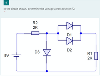
In the circuit shown, determine the voltage across resistor R2.
(Use 2nd approximation and assume all diodes are silicon for all the problems)

Transcribed Image Text:In the circuit shown, determine the voltage across resistor R2.
R2
2K
D1
D2
D3
R1
9V
2K
Expert Solution
This question has been solved!
Explore an expertly crafted, step-by-step solution for a thorough understanding of key concepts.
Step by stepSolved in 3 steps with 3 images

Knowledge Booster
Learn more about
Need a deep-dive on the concept behind this application? Look no further. Learn more about this topic, electrical-engineering and related others by exploring similar questions and additional content below.Similar questions
- help with multiple choicearrow_forwardThis about PN Junctions of semiconductors.arrow_forwardA p-type semiconductor joined to an n-type semiconductor ... Pick those that apply. Will not allow current to flow in either direction. Has electron current flowing from the n-type to the p-type material Makes a diode Allows positive current flow from the p-type to the n-type materialarrow_forward
- Q-2: The input signal for half-wave rectifier is a.c. signal. The output of 800 load resistor is 50V d.c. voltage. The diode has a resistance of 25 Q. 5 a) Draw the graphs of input signal, diode signal and output signals. 20 b) Calculate the maximum voltage value for the input signal. AC Supply Diode wwwarrow_forwarduse a P-N junction ideal diode to simulate a circuit measure and plot its I-V characteristics as well as its forward characteristics. assume breakdown voltage of around 6V for your calculations. I have added my multisim design with IV graph of the diode. I need : the large signal piece wise linear parameters of the diode. and for the plot do the theoretical calculations for at least one point on the curve and mark it on the curve This peoblem has other part that I will send when the expert answered this part. Tnxarrow_forwardUsing the ideal diode model, find the output voltage for the input voltage of the following circuit and graph it in detail. (a) (b) R₁ D₁ www ww R3 D2 (a) R₁ D₁ www + + D2 R2 vo Vo R₂ (b)arrow_forward
- Choose the doping material that will cause silicon to become a p-type semiconductor. A. Ge B. As C. Te D. Barrow_forwardFor the circuit shown below, sketch to scale the output V waveform and draw the transfer characteristic (V versus Vi), Assume the diodes are ideal.arrow_forwardThe four diodes used in a bridge rectifier circuit have forward resistances which may be considered constant at 1 ohm and infinite reverse resistance. The alternating supply voltage is 220 V r.m.s. and load resistance is 580 ohm. Calculate (i) mean load current and (ii) power dissipated in each diode.arrow_forward
- ....fast and fast..please..arrow_forwardWhat is he esuting cument in A06Cof electrical charge is transtemed in 42 ms Provide anumericaanwer without unt to at lest 2 decimal placesarrow_forward4.) In which mode will a diode generally not conduct electricity? a. Bidirectional Biased b. None of these c. Forward Biased d. Reversed Biased 5.) Consider the following schematic symbol of a semiconductor device: Which side is the Cathode? (Picture inserted down below) a. Side A b. Both side A and B c. Side B d. Neither side A or B 8.) Integrated circuits can be broken down into three basic categories. Which category does an operational amplifier (or op-amp) fall into? a. Analog b. None of these c. A combination of analog and digital d. Digitalarrow_forward
arrow_back_ios
SEE MORE QUESTIONS
arrow_forward_ios
Recommended textbooks for you
 Introductory Circuit Analysis (13th Edition)Electrical EngineeringISBN:9780133923605Author:Robert L. BoylestadPublisher:PEARSON
 Delmar's Standard Textbook Of ElectricityElectrical EngineeringISBN:9781337900348Author:Stephen L. HermanPublisher:Cengage Learning
 Programmable Logic ControllersElectrical EngineeringISBN:9780073373843Author:Frank D. PetruzellaPublisher:McGraw-Hill Education
 Fundamentals of Electric CircuitsElectrical EngineeringISBN:9780078028229Author:Charles K Alexander, Matthew SadikuPublisher:McGraw-Hill Education
 Electric Circuits. (11th Edition)Electrical EngineeringISBN:9780134746968Author:James W. Nilsson, Susan RiedelPublisher:PEARSON
 Engineering ElectromagneticsElectrical EngineeringISBN:9780078028151Author:Hayt, William H. (william Hart), Jr, BUCK, John A.Publisher:Mcgraw-hill Education,

Introductory Circuit Analysis (13th Edition)
Electrical Engineering
ISBN:9780133923605
Author:Robert L. Boylestad
Publisher:PEARSON

Delmar's Standard Textbook Of Electricity
Electrical Engineering
ISBN:9781337900348
Author:Stephen L. Herman
Publisher:Cengage Learning

Programmable Logic Controllers
Electrical Engineering
ISBN:9780073373843
Author:Frank D. Petruzella
Publisher:McGraw-Hill Education

Fundamentals of Electric Circuits
Electrical Engineering
ISBN:9780078028229
Author:Charles K Alexander, Matthew Sadiku
Publisher:McGraw-Hill Education

Electric Circuits. (11th Edition)
Electrical Engineering
ISBN:9780134746968
Author:James W. Nilsson, Susan Riedel
Publisher:PEARSON

Engineering Electromagnetics
Electrical Engineering
ISBN:9780078028151
Author:Hayt, William H. (william Hart), Jr, BUCK, John A.
Publisher:Mcgraw-hill Education,