
Introductory Circuit Analysis (13th Edition)
13th Edition
ISBN: 9780133923605
Author: Robert L. Boylestad
Publisher: PEARSON
expand_more
expand_more
format_list_bulleted
Related questions
Question
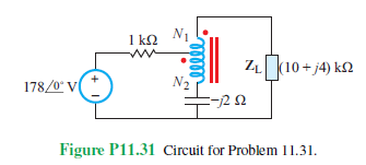

Transcribed Image Text:1 ΚΩ N₁
m
ZL (10+j4) ks2
178/0° V
N2
-202
Ω
Figure P11.31 Circuit for Problem 11.31.
Expert Solution
This question has been solved!
Explore an expertly crafted, step-by-step solution for a thorough understanding of key concepts.

Step by stepSolved in 2 steps with 1 images

Knowledge Booster

Similar questions
- in V1 R2 100k SINE(0 10 100) R1 100k D1 D V2 0 out D D2 V3 0 DC offset[V]: 0 Amplitude[V]: 10 Freq[Hz]: 100 T delay[s]: Theta[1/s]: Phi[deg]: Ncycles: anter 2019-2220 Figure 3-5 Clipper Circuit for LTSPICE Simulation C4. To specify the type of simulation, select "Simulate>>Edit Simulation Cmd" from the menu. Choose "Transient" and enter 30m for Stop time, 0 for Time to start saving data, and 1m for Maximum Timestep. Click OK. C5. Click Run to start the analysis. C6. Place two voltage probes (voltage probes appear when placed on a wire during simulation), one at the input side (at the top of V1) and another at the output side (at the top of D2) of the circuit. What difference do you observe between the input and the output waveforms?arrow_forwardFrom step1, how did you get that 50+(80*j60/80+j60) = 78.8+j38.4? also in step 2, how did you get that 5/(0.0125-0.0167) = 143.63 + j191.89?arrow_forwardPlease answer alll subparts for like either dislike...arrow_forward
- Why this happening to my circuit? I am inputting a 0-3.3 V sine wave into my voltage follower circuit using NE5532P. At the output I am seeing 0-3.3 V sine wave as expected. However, when I add a 1000 uF capacitor and a loudspeaker to listen to the sine wave my wave is clipped and its reading -800 mV for min and +680 mV for max on the oscilloscope. How do I fix this so that I only listen to 0-3.3 V sine wave? I'm in the lab and this is confusing to me.arrow_forwardI need help creating a graph in Excel for the tables below. It needs to be Vce vs Ic and plots the Ib average for each table. The averages are below. Please show step by step. V1 = 4V V2 (V) Ib (µA) Ic (mA) Ie (mA) Vce (mV) Beta 0 11.5 -0.00794 -0.00356 7.94 -0.000690434783 1 11.1 0.701 -0.712 299 0.0631531532 2 11.1 0.711 -0.722 1290 0.0640540541 Table 1: V1 = 4, V2= 0-2 V V1 = 6V V2 (V) Ib (µA) Ic (mA) Ie (mA) Vce (mV) Beta 0 18.1 -0.0105 -0.00761 10.5 -0.000580110497 1 17.8 0.856 -0.874 144 0.0480898876 2 17.8 1.20 -1.22 797 0.0674157303 3 17.8 1.22 -1.25 1780 0.0685393258 Table 2: V1 = 6, V2= 0-3 V V1 = 8V V2 (V) Ib (µA) Ic (mA) Ie (mA) Vce (mV) Beta 0 24.7 -0.0123 -0.0125 12.3 -0.000497975709 1 24.5 0.878 -0.903 122 0.0358367347 2 24.4 1.71 -1.73 291 0.0700819672 4 24.4…arrow_forwardQUESTION 3 An inductor, a capacitor, and a resistor are connected in series with a function generator. The inductor drops 5V RMS, the capacitor drops 20V RMS, and the resistor drops 2V RMS. Find the magnitude of the total voltage. O 27V RMS O 15V RMS O 38V RMS O 9V RMSarrow_forward
- how to measure ripple factor and peak input and peak output voltage for this circuits ?arrow_forwardShow step by step solution and write legibly.arrow_forwardA certain impedance is given by 1012° N. Does the current lead or lag the voltage, and by how many degrees? Fill in the blanks. The current the voltage byarrow_forward
- QUESTION 3 An inductor, a capacitor, and a resistor are connected in parallel with a function generator. The inductor draws 100mA RMS, the capacitor draws 150mA RMS, and the resistor draws 200mA RMS. Find the magnitude of the total current. O 450mA RMS O 544mA RMS O 352mA RMS O 206mA RMSarrow_forwardWhat's 21 22 23arrow_forwardAc - 100 VrmsR1 - 1kR2 - 500Rload - 1kCapacitor - 2uF Q1. How much is the capacitor voltage lagging from the AC sourcearrow_forward
arrow_back_ios
SEE MORE QUESTIONS
arrow_forward_ios
Recommended textbooks for you
- Introductory Circuit Analysis (13th Edition)Electrical EngineeringISBN:9780133923605Author:Robert L. BoylestadPublisher:PEARSON
 Delmar's Standard Textbook Of ElectricityElectrical EngineeringISBN:9781337900348Author:Stephen L. HermanPublisher:Cengage Learning
 Programmable Logic ControllersElectrical EngineeringISBN:9780073373843Author:Frank D. PetruzellaPublisher:McGraw-Hill Education
  Fundamentals of Electric CircuitsElectrical EngineeringISBN:9780078028229Author:Charles K Alexander, Matthew SadikuPublisher:McGraw-Hill Education
 Electric Circuits. (11th Edition)Electrical EngineeringISBN:9780134746968Author:James W. Nilsson, Susan RiedelPublisher:PEARSON
 Engineering ElectromagneticsElectrical EngineeringISBN:9780078028151Author:Hayt, William H. (william Hart), Jr, BUCK, John A.Publisher:Mcgraw-hill Education,
Introductory Circuit Analysis (13th Edition)
Electrical Engineering
ISBN:9780133923605
Author:Robert L. Boylestad
Publisher:PEARSON
Delmar's Standard Textbook Of Electricity
Electrical Engineering
ISBN:9781337900348
Author:Stephen L. Herman
Publisher:Cengage Learning
Programmable Logic Controllers
Electrical Engineering
ISBN:9780073373843
Author:Frank D. Petruzella
Publisher:McGraw-Hill Education
Fundamentals of Electric Circuits
Electrical Engineering
ISBN:9780078028229
Author:Charles K Alexander, Matthew Sadiku
Publisher:McGraw-Hill Education
Electric Circuits. (11th Edition)
Electrical Engineering
ISBN:9780134746968
Author:James W. Nilsson, Susan Riedel
Publisher:PEARSON
Engineering Electromagnetics
Electrical Engineering
ISBN:9780078028151
Author:Hayt, William H. (william Hart), Jr, BUCK, John A.
Publisher:Mcgraw-hill Education,