
Delmar's Standard Textbook Of Electricity
7th Edition
ISBN: 9781337900348
Author: Stephen L. Herman
Publisher: Cengage Learning
expand_more
expand_more
format_list_bulleted
Related questions
Question

Transcribed Image Text:1 ΚΩ
B
(+-
10V
2 ΚΩ
13mA
E
12 V
4 mA
ww
4ΚΩ
D
6 mA
2ΚΩ
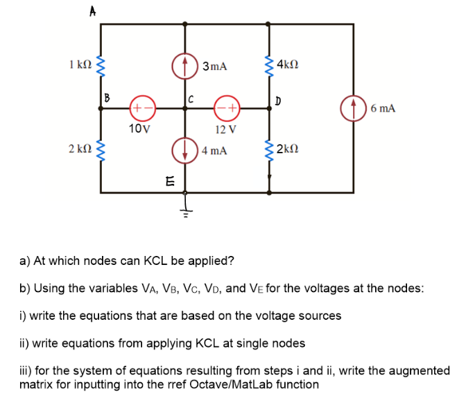
a) At which nodes can KCL be applied?
b) Using the variables VA, VB, VC, VD, and VE for the voltages at the nodes:
i) write the equations that are based on the voltage sources
ii) write equations from applying KCL at single nodes
iii) for the system of equations resulting from steps i and ii, write the augmented
matrix for inputting into the rref Octave/MatLab function
Expert Solution
This question has been solved!
Explore an expertly crafted, step-by-step solution for a thorough understanding of key concepts.

Step by stepSolved in 2 steps

Knowledge Booster

Similar questions
- Please in typing format please ASAP for the like Please answer the same toarrow_forwardElectrical engineeringarrow_forward(a) Use Ohm's Law to derive an expression relating Vout to Vin using the values of the two resistors. For this calculation, assume that you have no load attached (i.e. RL → xx). Make sure to explain in words each step you take. Hint: Vout is just the voltage drop across R2. You can draw in a battery with AV = Vin if that helps you set up the relationships. R1 Vin R2 Vout (O Vin- Your answer should be in the form, Vout The term in parentheses is called the gain of the divider, or the divider ratio. in· wwarrow_forward
- only 11arrow_forwardconsider the following circuit composed of three resistors and two batteries. each resistor has a resistance of 2.00 ohms. assume that the branch currents flow in the directions indicated in the figure. note that: I = 0.600 A I = 0.800 A E1= 10.0V R1= 10 ohms R3= 5 ohms Solve: a.) Write out the equation relating the currents by using the junction rule at node a. Additionally, what is the magnitude of I3? b.) What is the resistance of R2? c.) what is E2?arrow_forwardKnowing the resistance of the resistors and the EMF of the sources, find the currents in the branches.Proceed comparative analysiswith calculation (equations) and mathematical analysis (Ansys). Create reports with calculations (current on each elements, voltage on each elements), screenshot from Ansys and conclusion. my c variant is 2arrow_forward
- Find the equivalent resistance across the ports A and B (in ohms to 2 decimal places)V2 is a dependent voltage source the equation for which is: V2 = 5Vr3 (where vr3 is the voltage over the resistor R3)Other required valuesV1 = 15VI3 = 5AR1 = 62 ohmsR2 = 32 ohmsR3 = 53 ohmsR4 = 60 ohmsR5 = 6 ohmsR6 = 90 ohmsarrow_forwardA Wheatstone bridge is used for measuriug the valuc of change of resistance of a strain gauge wnich forms one of the arms of the bridge. All tbe arms of the bridge including the strain gauge have a resistance of 100 N each. The maximum a!lowable power dissipation from the strain gauge is 250 mW. Determine the value of maximu:n permissible current through the strain gauge and maximum allowable value of bridge supply voltage. Suppose a source of 20 V is available, lind the value of series resistance to be connected between the source and the bridge to limit the input voltage of the bridge to permissible level.arrow_forwardSample Problem continued with solution process Step 1: Drawing a circuit diagram and labeling the unknowns. All told there are 5 elements, 4 resistors and 1 voltage source. For resistors I intentionally label the currents going from + to -. That way, I can write V = I R. If I labeled the current through a resistor from – to + as I, then I have to write the equation by Ohm's law as V = -I R. For convenience I label the current i, through the voltage source from – to +. (There is no Ohm's law for a source to follow. Do not try to have a resistance in a source. What is a V, 3 + (1 |1A 10 Ω + V, iş V2 20 i2 V3 + 2 20Ω 4 İz I then examine the circuit. I see that this is a obvious consequence of the labeling: iz = i,= i, All are current going through one path with the same direction as I labeled. If I had labeled one in the opposite direction, I just had to put in a minus sign. source? A voltage source is to guarantee the voltage drop from its + to its – a fixed voltage V,. I denote four…arrow_forward
- could you help me please it's one questionarrow_forwardlell L1 R Ro 2. In this figure, assume arbitrary numbers for R1, R2, L1, and L2 including some number for the battery E. Find the rate of current in which inductor one (L1) is changing just after the switch is closed. Next, find the current in L1 after some time after the switch has been closed. lellarrow_forwardA potentiometer consisting of a wire of length L0 has a source of emf, ɛ connected across it. When a standard cell with emf V = 6V, in series with a voltmeter, is connected at one end of the wire and at a distance L = 4 cm along the wire the voltmeter circuit is in balance and the voltmeter reads zero. When the standard cell is replaced by a source of unknown emf the new balance length is found to be 6 cm. What is the unknown emf? Select one: a. 8 V b. 9 V c. 4 V d. 3 Varrow_forward
arrow_back_ios
SEE MORE QUESTIONS
arrow_forward_ios
Recommended textbooks for you
- Delmar's Standard Textbook Of ElectricityElectrical EngineeringISBN:9781337900348Author:Stephen L. HermanPublisher:Cengage Learning
Delmar's Standard Textbook Of Electricity
Electrical Engineering
ISBN:9781337900348
Author:Stephen L. Herman
Publisher:Cengage Learning