Power System Analysis and Design (MindTap Course List)
6th Edition
ISBN: 9781305632134
Author: J. Duncan Glover, Thomas Overbye, Mulukutla S. Sarma
Publisher: Cengage Learning
expand_more
expand_more
format_list_bulleted
Question
thumb_up100%
just a, b, c

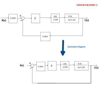
Transcribed Image Text:CONFIGURATION 2
150
0.16
3.1831
K
R(s)
s+150
s(s+1.32)
C(s)
3.1831
Equivalent diagram
150
0.16
R(s)
K
3.1831
S+150
s(s+1.32)
C(s)

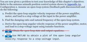
Transcribed Image Text:You are now given a problem to test your knowledge of this chapter's objectives.
Refer to the antenna azimuth position control system shown in Appendix A2,
Configuration 2. Assume an open-loop system (feedback path disconnected) and
do the following:
a. Predict the open-loop angular velocity response of the power amplifier,
motor, and load to a step voltage at the input to the power amplifier.
b. Find the damping ratio and natural frequency of the open-loop system.
c. Derive the open-loop angular velocity response of the power amplifier, motor,
and load to a step-voltage input using transfer functions.
d.
e.
State Space
SS
MATLAB
ML
Obtain the open-loop state and output equations.
Use MATLAB to obtain a plot of the open-loop angular
velocity response to a step-voltage input.
Expert Solution
This question has been solved!
Explore an expertly crafted, step-by-step solution for a thorough understanding of key concepts.
Step by stepSolved in 2 steps with 1 images

Knowledge Booster
Similar questions
- From the phasor diagram in the figure, deduce a expression for the output power, as a function of the armature current, Ia, and angle γ . Draw the curve Power (P) versus current angle (γ), for different levels of excitement Ef. For this consider negligible mechanical losses.arrow_forwardNonearrow_forwardWhat is the use of DC-DC boost module 0.9-5v to 5v? How does it work?arrow_forward
- Hybrid vehicle. FIGURE P1 shows the block diagram of a possible cascade control scheme for an HEV driven by a dc motor (Preitl, 2007). The block diagram of the speed control of an HEV taken from FIGURE P1, and rearranged as a unity feedback system is shown in FIGURE P2. Here the system output is C(s) = Kss V(s), the output voltage of the speed sensor/transducer. pC, Av,- Speed K, Gre(s) controller command Torque Amplifier controller output & power voltage amplifier Acro- Motive dynamie Armature Speed |drag torque Angular speed, Ref. circuit Armature torque Vehicle signal R,(s). error U(s) T(s)T,(s) current E,(s) speed, V(s) Gse(s) K, Grc(s) R. tot Friction Feedback speed signal Kss2(s) Feedback torque current signal Kes I(S) T,(s) E,(s) Back emf D=k ks Current sensor sensitivity Kcs Speed sensor sensitivity Kss FIGURE P1 Hybrid Vehicle R (s), E (s) Uc(s) |C(s) + Gsc(s) 0.11 (s + 0.6) SC s (s + 0.5173) + 5 (s + 0.6) (s + 0.01908) URE P2 Block diagram of the speed control of an HEV a.…arrow_forwardQ6 Consider the motor position control system shown in Figure Q6 (a). The system includes the velocity feedback (Gain Kg) to form a PD-type control action. (a) Find Kg and Kc to obtain a system damping ratio 0.5 and steady-state error 0.05 for step input T1. Assume input coming from R(s) = 0. (b) The above control scheme has been modified by adding an integrator (see Figure Q6 (b)). Assume K-8.0 and Kg-0.79, use Routh-Hurwitz criterion to determine the limiting value of K; for absolute stability.arrow_forwardwhat is mean by phase angle control method?arrow_forward
- Why the power factor is low in the open circuit test?arrow_forwardThe speed of a separately excited dc motor is controlled by a single-phase full-wave converter in figure below. The field circuit is also controlled by a full converter and the field current is set to the maximum possible value. The ac supply voltage to the armature and field converters is one phase, 430 V, 60 Hz. The armature resistance is Ra = 0.215 SN, the field circuit resistance is Rf = 125 N, and the motor voltage constant is K, 0.825 V/A rad/s. The armature current corresponding to the load demand is la = 45 A. The viscous friction and no-load losses are negligible. The inductances of the armature and field circuits are sufficient to make the armature and field currents continuous and ripple free. If the delay angle of the armature converter is aa = 40 ° and the armature current is I. = 32 А. • Determine the torque developed by the motor Ta. i. A1 F1 for 0 s a, ST 2Vm Ta La Ra N.m cos aa TT Va • Determine the motor speed. Rf for 0 s afS T M 2Vm N rpm F2 V; = Cos af TT A2 (a)…arrow_forwardWhat are the disadvantages of the power factor correction?arrow_forward
- Q3) A speed control system of a DC motor with a -ve feedback is shown in the figure below The input R(s) and the output w(s) Km 1 K (Ra – Las) (Js + b) back emf signal a) Derive the closed loop transfer function. Assume Ra = La =J = b = 1 and the motor constants Km = K, = 2 b) Calculate the steady stat error of his system to a step input command. c) Select a feedback gain for the back emf signal to yield a step response with an overshoot of 15%.arrow_forwardQ2:A common actuator in control systems is the DC motor, determine the transfer function of the armature-controlled DC motor system described below. Represent the transfer function in terms of the input voltage (V) and the output angular velocity 0. Where T = Ki and e = Kė. Suter winding Angk Bearings R Bruss Armature P circuit Rotor Fixed fieldarrow_forwardA single phase Half wave AC voltage controller has a resistive load of 16 ohms with input supply voltage of 240 V, 50 Hz. The delay angle of the thyristors is, a = 2T/5. Determine a) The rms output voltage and current. b) Input power factor and Input curren c) Average output voltage and current.arrow_forward
arrow_back_ios
SEE MORE QUESTIONS
arrow_forward_ios
Recommended textbooks for you
 Power System Analysis and Design (MindTap Course ...Electrical EngineeringISBN:9781305632134Author:J. Duncan Glover, Thomas Overbye, Mulukutla S. SarmaPublisher:Cengage Learning

Power System Analysis and Design (MindTap Course ...
Electrical Engineering
ISBN:9781305632134
Author:J. Duncan Glover, Thomas Overbye, Mulukutla S. Sarma
Publisher:Cengage Learning