
Concept explainers
(a)
The value of
(a)
Answer to Problem 8.9EP
The value of the bias current is
Explanation of Solution
Calculation:
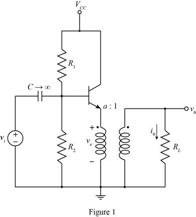
The given diagram is shown in Figure 1
The conversion from
The expression for the value of the base to emitter to voltage is given by,
Substitute
The expression for the bias current is given by,
Substitute
Conclusion:
Therefore, the value of the bias current is
(b)
The value of
(b)
Answer to Problem 8.9EP
The value of current
Explanation of Solution
Calculation:
The value of peak voltage and output voltage are equal and the expression for the value of the load current is given by,
Substitute
The expression for the emitter current for3 the
Substitute
The expression for the base current of the
Substitute
The expression for the collector current of
Substitute
The conversion from
The conversion from
The conversion from
The expression to determine the value of the diode current is given by,
Substitute
The value of the collector current for
Substitute
The expression for the base emitter voltage of
Substitute
The expression for the value of
Substitute
The expression for the base emitter voltage of
Substitute
The expression for the collector current
Substitute
Conclusion:
Therefore, the value of current
(c)
The value of
(c)
Answer to Problem 8.9EP
The value of current
Explanation of Solution
Calculation:
The value of peak voltage and output voltage are equal and the expression for the value of the load current is given by,
Substitute
The expression for the emitter current for3 the
Substitute
The expression for the base current of the
Substitute
The expression for the collector current of
Substitute
The conversion from
The conversion from
The expression to determine the value of the diode current is given by,
Substitute
The value of the collector current for
Substitute
The expression for the base emitter voltage of
Substitute
The expression for the value of
Substitute
The expression for the base emitter voltage of
Substitute
The expression for the collector current
Substitute
Conclusion:
Therefore, the value of current
Want to see more full solutions like this?
Chapter 8 Solutions
Microelectronics: Circuit Analysis and Design


- For the circuit shown in Figure, consider Ideal diodes. If Vs = 19sin wt, Vb = 4 V, the minimum value of output voltage is: Vout at of estion Vs Vb Oa. -4 V Ob. -15 V Oc. -19 V Od. 4 Varrow_forwarde average voltage of Vo. 5 URM U 2 Figure B.2 shows a circuit using two silicon diodes with knee voltage of 0.7 V. The supply voltage, Vs, is a sinusoidal AC signal. The produced output, Vo, is a fluctuating DC signal with ripple peak-to-peak voltage of I.58 V. & UTM UTM UTM STM DI 5 UTM O UTM 50 Hz &UTM UTM UTM 5 UTM UTM UTM 50 µF RL UTM & UTM D2 &UTM/ UTMTUTM (a) Determine the SITM (b) Determine the peak voltage of the Vs. 5 UTM (c) Consider UTM &UTM & UTM waveform of Vo with complete labelling. en Ci is removed from the circuit (i.e. open circuit). Draw the 5 UTM & UTM UTM U1 A TM 5 UTM UTM TM 5 UTM UTMarrow_forward8 UTM Figure B.1 shows a diode circuit and its DC load line analysis. Based on the SUT information obtained UT UT I kQ + VpQ- 3 UTM UTM Vs 3 500 2 UTM & UM TM &UTM UTM UTM &UTM 5 UTM Figure B.1 UTM & U UTM VD (V) 0.72 UTM i UTM UTMarrow_forward
- Consider the following circuit (See image):Show that it is a unity gain absolute value circuit, consider ideal diodesarrow_forward1. For a 60Hz, 9Vms AC input, with 250 Ohms load, determine VDc across the load, for FWR power supply, (show the required circuit). Draw the waveform on the load. 2. If C=200uf, filter capacitor is applied across the load: Calculate Vpp ripple and VDc, for the load. 3. Determine PIV on the diodes 4. If one of the diodes become open, what would be VDc and V, load. across the load, with & without capacitor. Draw the waveform on the fms,arrow_forward8.What is the effect of increasing the value of the capacitance In single phase half wave with RL 9. Give an example of a practical case of half-wave uncontrolled rectifier with RL load connected in parallel with C. 10. Propose another circuit(s) to convert AC signal to DC signal.arrow_forward
- Figure shows a composite switch consisting of a power transistor (BJT) in series with a diode. Assuming that the transistor switch and the diode are ideal, the I-V characteristic of the composite switch isarrow_forwardA simple diode rectifier has 'ripples' in the output wave which makes it unsuitable as a DC source. To overcome this one can use a capacitor in series with a the load resistance. Select one: O True O False Fixed bias is less stable than Voltage divider bias in transistor biasing techniques. Select one: O True O Falsearrow_forward3 A peak rectifier (peak tollower) Cir cuit is gian below. Vs is a GOH3 Sinuscidal Vollge with peak value Upz50V. 50V. The load resistance R= Sk . Find the Vallke of the capacitance C Such that the peak- to-peak ripple 2 volts. (idenl diede) Voltage Vr Vsarrow_forward
- Set up a midpoint bias for a JFET with IDSS = 14 mA and VGS(off) = -10 V. Use a 24 V dc source as the supply voltage. Show the circuit and resistor values. Indicate the value of ID. Indicate the value of VGS. Indicate the value of VDS.arrow_forwardANSWER ALL WILL UPVOTE IF CORRECT 7. What is the maximum conduction angle for an SCR? a. 90, b. variable, c. 180, d.360 8. A breakover type of device can be represented as a long resistor with a diode tapped somewhere in the middle. a. SCR, b. BJT, c. FET, d. UJT 9. It is the ratio of the resistance at the base1 terminal to the resistance across the two bases. a. base resistance ratio, b. interbase resistance ratio, c. intrinsic standoff ratio, d. intrinsic resistance ratio 10. the duration (in degrees) of an AC cycle that the SCR is turned on a. turn on angle, b. firing angle, c. conduction angle, d. firing delay anglearrow_forwardSilicon BJT (β=120) and Germanium BJT (β=120) VCE in circuitCalculate its value. Comment the circuitarrow_forward
 Introductory Circuit Analysis (13th Edition)Electrical EngineeringISBN:9780133923605Author:Robert L. BoylestadPublisher:PEARSON
 Delmar's Standard Textbook Of ElectricityElectrical EngineeringISBN:9781337900348Author:Stephen L. HermanPublisher:Cengage Learning
 Programmable Logic ControllersElectrical EngineeringISBN:9780073373843Author:Frank D. PetruzellaPublisher:McGraw-Hill Education
 Fundamentals of Electric CircuitsElectrical EngineeringISBN:9780078028229Author:Charles K Alexander, Matthew SadikuPublisher:McGraw-Hill Education
 Electric Circuits. (11th Edition)Electrical EngineeringISBN:9780134746968Author:James W. Nilsson, Susan RiedelPublisher:PEARSON
 Engineering ElectromagneticsElectrical EngineeringISBN:9780078028151Author:Hayt, William H. (william Hart), Jr, BUCK, John A.Publisher:Mcgraw-hill Education,