
Videos
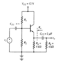
For the circuit in Figure P7.21, the transistor parameters are
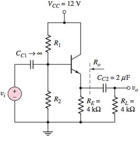
Figure P7.21
a.
To design: The bias stable circuit for the given condition.
Explanation of Solution
Given:
The circuit is given as:
IEQ =1.5mA.
The parameters of the circuit is given as:
The design needed for the bias stability is given as:
Recalling the general rule that the circuit is considered to be stable only, if:
Evaluating the Thevenin resistance
Substituting the known values in the equation:
Evaluating the value of base current
Substituting the known values in the above equation:
The expression for Thevenin s voltage
Substituting the known values in the above equation:
The other expression for Thevenin s voltage
Substituting the known values in the above equation:
The value of resistance
Substituting the known values in the above equation:
Therefore, the designed values are:
b.
The small signal mid band voltage gain.
Answer to Problem 7.21P
The value of voltage gain
Explanation of Solution
Given:
The circuit is given as:

IEQ =1.5mA.
The parameters of the circuit is given as:
Evaluating the value of collector current
Substituting the known values:
Evaluating the value of
Substituting the known values into the above equation:
Evaluating the value of output resistance
Substituting the known values into the above equation:
Evaluating the value of voltage gain
Substituting the known values into the above equation:
Therefore, the value of voltage gain
c.
The value of the output resistance.
Answer to Problem 7.21P
The value of output resistance
Explanation of Solution
Given:
The circuit is given as:

IEQ =1.5mA.
The parameters of the circuit is given as:
Evaluating the output resistance
Substituting the known values into the above equation:
Therefore, the value of output resistance
d.
The lower 3dB corner frequency for the given circuit.
Answer to Problem 7.21P
The value of lower corner frequency is 19.81Hz.
Explanation of Solution
Given:
The circuit is given as:

IEQ =1.5mA.
The parameters of the circuit is given as:
Evaluating the value of lower 3dB corner frequency:
Substituting the known values to the above equation:
Hence, the value of lower corner frequency is 19.81Hz.
Want to see more full solutions like this?
Chapter 7 Solutions
Microelectronics: Circuit Analysis and Design


- In order to express the effect of the internal capacitors of BJT and the high frequency reception, the current gain expression depending on the frequency (Figure b) (hfe) is used in the case of collector emitter short circuit, voltage source connected at base end and emitter grounded (Figure la).. The catalog information of the 2N2222 transistor is given in Figure Ic. In the catalogue, when Ic=20 mA, it is seen as fT=250 MHz. a) Find the total capacitor effect for the case where gm> > wCμ. (Cpi) + (Cμ) = ?pFarrow_forward. Draw the d.c load line for the circuit diagram shown below. What will be the Q point if zero signal base current is 30 µA and β = 50?arrow_forwardDescribe the combined effect of the RC circuits for higher frequency response in a BJT & FETamplifier. the subject : Analogue Electronics IIarrow_forward
- Given the MOSFET in Figure 6 has bran) = 200 mA at VGs = 4 V and V(Tn) = 2 V; i. Plot the transfer characteristic curve for the MOSFET. b) i. Determine the operating point Vasa, Ioa and Vosa for the circuit. ii. Calculate the value of the transconductance gm at the Q-point. iv. Determine the voltage gain and input impedance of the amplifier. 15 V 1 kn. Coe 1.5 M2. Cin 33 kn. Vn 30 ka Figure 6arrow_forwardCoonsider the common emitter amplifier shown in figure below. Assume a β of 100, VBE = 0.7V, VT = 25mA and VA = 100V. Draw an equivalent DC model and determine the rπ, transconductance (gm) and ro. Draw an equaivalent AC model using the small-signal model Find an expression for vbe and vo in terms of the input voltagearrow_forwardQuestion 6 A large signal circuit model for a MOSFET consists of a dependent current source in parallel with an output resistance, ro, where ro can be expressed as 1/1lp or VA/ID. True Falsearrow_forward
- Problem 01: Draw a real-life MOSFET circuit(Ac model) and derive the circuit in that circuit to find operating region, circuit biasing, Ac model, and frequency response curve.arrow_forwardVs=100 mV peak-to-peak, 1 kHz sine signal, Kn=0.4mA/v^2 ,Vt=1V , λ=0.01V^-1 Make the DC analysis of the above given mosfet amplifier circuit. Simulation to tableWrite down the measured values and mathematical calculation results. (The valueswith the units.)DC Parameters ,Measured value ,Calculated ValueVGETCVGSVDVDSIDb. Draw the small signal model for the AC analysis of the circuit. Find the gm, ro, Av values.c. Show the Vs input signal and the Vo output signal of the circuit on the oscilloscope. Volt/div of channels andSpecify time/div values.arrow_forward1.The voltage measured from the collector to the emitter is the sum of the voltage base-emitter plus the voltage collector-base. Select one: True Or False 2.A decrease in base current of a C-E amplifier causes the voltage measured between the emitter and the collector to increase. Select one: True Or False 3.A FET is ..............controlled device whereas a bipolar transistor is a.............controlled device. Answer:arrow_forward
- In the small signal model of a MOSFET, where are the most prominent parasitic capacitances? O a. Between source-body and gate-drain O b. Between gate-source and gate-drain c. Between drain-source and source-body d. Between gate-source and source-drainarrow_forwardPercent (%) Total Harmonic Distortion of Signal Equal to which of the following.arrow_forwardThe modulating index of an AM-signal is reduced from 0.8 to 0.5. The ratio of the total power in the new modulated signal to that of the original signal will nearly bearrow_forward
 Introductory Circuit Analysis (13th Edition)Electrical EngineeringISBN:9780133923605Author:Robert L. BoylestadPublisher:PEARSON
 Delmar's Standard Textbook Of ElectricityElectrical EngineeringISBN:9781337900348Author:Stephen L. HermanPublisher:Cengage Learning
 Programmable Logic ControllersElectrical EngineeringISBN:9780073373843Author:Frank D. PetruzellaPublisher:McGraw-Hill Education
 Fundamentals of Electric CircuitsElectrical EngineeringISBN:9780078028229Author:Charles K Alexander, Matthew SadikuPublisher:McGraw-Hill Education
 Electric Circuits. (11th Edition)Electrical EngineeringISBN:9780134746968Author:James W. Nilsson, Susan RiedelPublisher:PEARSON
 Engineering ElectromagneticsElectrical EngineeringISBN:9780078028151Author:Hayt, William H. (william Hart), Jr, BUCK, John A.Publisher:Mcgraw-hill Education,