
Concept explainers
Videos
The demonstration of how rapidly Rayleigh’s method converges for the uniform-diameter solid shaft.
Answer to Problem 29P
The Rayleigh method for uniform diameter shaft is converging rapidly by using a static deflection beam equation.
Explanation of Solution
Write the expression for moment of inertia.
Here, the diameter of the shaft is
Write the expression for area of the shaft.
Write the expression for weight of the shaft.
Here, the specific weight is
Write the expression for influence coefficient.
Here, the length of the shaft is
Write the expression for deflection at point 1.
Write the expression for Rayleigh method.
Write the expression for Rayleigh method.
Write the expression for first critical speed.
Draw the diagram for the two elements system.
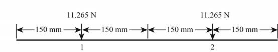
Figure-(1)
The figure-(1) shows the required dimension.
Write the expression for the deflection at point 1 for two element.
Write the expression for the deflection at point 2 for two element.
Write the expression for Rayleigh method for two element.
Write the expression for Rayleigh method for two element.
Write the expression for first critical speed for two element.
Draw the diagram for the three element system.
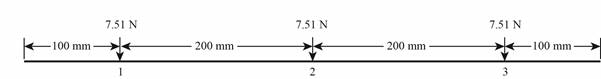
Figure-(2)
The Figure-(2) shows all the dimensions for the three elements.
Write the expression for the deflection at point 1 for three elements
Write the expression for the deflection at point 2 for three element.
Write the expression for the deflection at point 2 for three element.
Write the expression for Rayleigh method for three elements.
Write the expression for Rayleigh method for three elements.
Write the expression for first critical speed for three elements.
Conclusion:
Substitute
Substitute
Substitute
Substitute
Substitute
Calculate the square of the deflection at point 1 of element 1.
Substitute
Substitute
Substitute
Substitute
Substitute
Substitute
Substitute
Substitute
Substitute
Calculate the square of the deflection at point 1 of element 2.
Calculate the square of the deflection at point 2 of element 2.
Substitute
Substitute
Substitute
Substitute
Substitute
Substitute
Substitute
Substitute
Substitute
Substitute
Substitute
Substitute
Calculate the square of the deflection at point 1 of element 3.
Calculate the square of the deflection at point 2 of element 3.
Calculate the square of the deflection at point 3 of element 3.
Substitute
Substitute
Substitute
Since the static bending equation is available, and satisfied the moment-free and deflection-free ends, so the convergence is rapid using a static deflection beam equation.
Thus, the Rayleigh method for uniform diameter shaft is converging rapidly by using a static deflection beam equation.
Want to see more full solutions like this?
Chapter 7 Solutions
Shigley's Mechanical Engineering Design (McGraw-Hill Series in Mechanical Engineering)


- A shaft in torsion only is to transmit 2500 HP at 570 rpm with mild shock. Its material is AISI 1137 steel annealed. (a) What should be the diameter of a solid shaft? (b) If the shaft is hollow, Do = 2Di, what size is required? (c) What is the weight per foot of length of each of these shafts? Which is lighter? Use sp. weight = 0.286 Ibs/cu. in. (d) Which shaft is more rigid? Compute the torsional deflection of each shaft for a length of 10 ft.arrow_forwardBearing stress 5. Please provide proper discussion and illustration also complete solution and clear solution please thank you A solid shaft is designed to transmit 50kN @ 1800 rpm to a gear by means of 156 mm long key with square cross-section. The shaft diameter is 35.6mm. What should the cross-section be in mm2 to resist shearing, if the allowable shear stress on the key is 20 MPa?arrow_forwardFigure below shows a rotating shaft simply supported in ball bearings at A and D and loaded by a nonrotating orce Fof 6.8 kN. Using ASTM "minimum" strengths, estimate the life of the part. 6T td7 (a) Shaft drawing showing all dimensions in millimeters; all fillets 3-mm radius. The shaft rotates and the load is stationary; material is machined from AISI 1050 cold-drawn steel. (b) Bending moment diagram.arrow_forward
- The rotating solid steel shaft is simply supported by bearings at points B and C and is driven by a gear (not shown) which meshes with the spur gear at D, which 250 mm has a 150 mm pitch diameter. The force F from the drive gear acts at a pressure angle of 20°. The shaft transmits a torque to point A of T = 340 N. m. The shaft 100 mm is machined from steel with S, = 420 MPa. Using a factor of safety of 2.5, determine the minimum allowable diameter of the 250 mm section of the shaft based on a static yield analysis using the distortion energy theory and maximum shear stress theory.arrow_forwardwith diameter d = 38 mm transmits 37 kW to a gear Calculate the required speed of rotation (number of at B. The allowable shear stress in the steel is 40 MPa. X7-3 A motor driving a solid circular steel shaft revolutions per minute) so that the shear stress in the shaft does not exceed the allowable limit. Motor d = 38 mm Barrow_forwardA hollow shaft made from AISI 4340 steel has an outer diameter D. of 4 in. and an inner diameter Di of 2.5 in. The shaft rotates at 46 rpm for one hour each day. It is supported by two bearings and loaded in the middle with a load W of 5500 lbf. The distance between the bearings Lis 78 in. The maximum tensile stress due to bending for this type of cyclic loading is calculated using the following equation: 8WLD, #(Dg – D{) What is the stress ratio for this type of cyclic loading? Would this shaft last for one year assuming a safety factor of 2?arrow_forward
- Solve the following problem Two designs for a shaft are being considered. Both have an outside diameter of 70 m and are 900 mm long. One is solid but the other is hollow with an internal diameter of 50 mm. Both are made from steel (G=120 GPa). Critically evaluate and compare the torsional shear stress, angle of twist of the two designs if they are subjected to a torque of T N. m. the missing Torque 325(T).arrow_forward3:35 PM Wed Dec 15 7 51% A power transmission shaft is to carry a steady 30 horsepower while rotating at 1000 rpm. Specify a suitable diameter for the solid circular shaft if it is to be made from AISI 1020 cold-drawn steel. Use Appendix A-2 for preferred size. 61arrow_forwardThe disc clutch of an automobile is carried on a 2-inch 6-splined shaft and not to slide under load. The nominal dimensions are as follows: b = 0.25 D; t = 0.075 D and d = 0.85 D. The hub length of 150 % of shaft diameter. Determine the total horsepower transmitted at 3,600 rpm, if the yield strength of the shaft is 1,400 psiarrow_forward
- A solid rotating shaft made of Annealed AISI 1030 is used in a boat with a high speed as shown in the figure. The transmitted power is 224 KW with Revolutions number 130 rpm. Use the failure criteria to determine the shaft diameter and which one is more conservative. Take n=1 and endurance limit 18.86 Kpsi. Ma 100 mm 9.75 marrow_forwardA alm T 1.20 m T B 1.20 m C 3 T The 60 mm diameter shaft is made of 6061-T6 aluminum having an allowable shear stress of Tallow 80 MPa. Find the corresponding angle of twist of disk A relative to disk C. Note: You will need to calculate the maximum allowable torque T first. Provide your answer for angle of twist in radians with 3 significant figures after the decimal point.arrow_forwardDesign a rigid flange coupling to transmit a torque of 228N-m between two coaxial shafts. The shaft is made of alloy steel, flanges out of cast iron and bolts out of steel. Four bolts are used to couple the flanges. The shafts are keyed to the flange hub. The permissible stresses are given below: Shear stress on shaft =100MPa Bearing or crushing stress on shaft =250MPa Shear stress on keys =100MPa Bearing stress on keys = 250MPa Shearing stress on cast iron = 200Mpa Shear stress on bolts =100MPa > Provide FBDarrow_forward
 Mechanics of Materials (MindTap Course List)Mechanical EngineeringISBN:9781337093347Author:Barry J. Goodno, James M. GerePublisher:Cengage Learning