
Videos
In each case, identify any two-force members, and then draw the free body diagrams of each member of the frame.
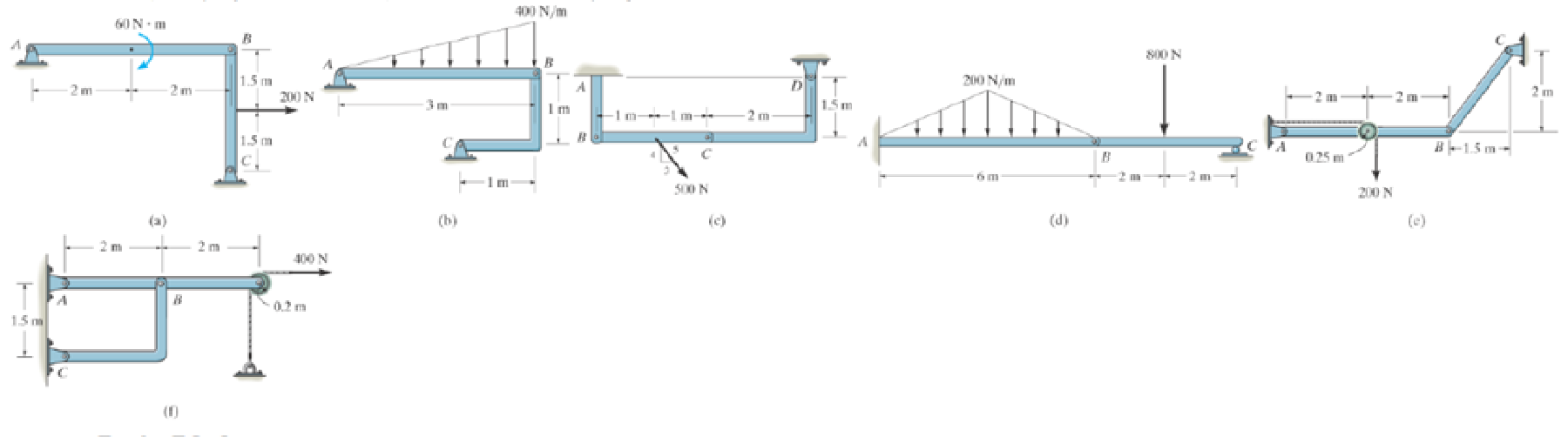
Prob. P6-3
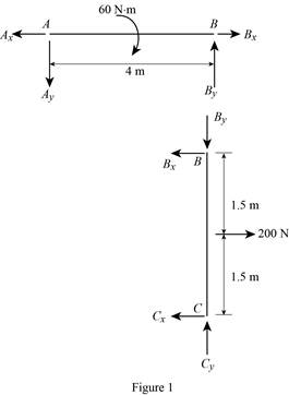
(a)
To identify and draw: The two force members and the free body diagrams of each member of the frame.
Explanation of Solution
Assumptions:
- Consider the state of member as tension where the force is pulling the member and as compression where the force is pushing the member.
- Consider the force indicating right side as positive and left side as negative in horizontal components of forces.
- Consider the force indicating upside is taken as positive and downside as negative in vertical components of forces.
Show the free body diagram of the member of the frame as in Figure (1).
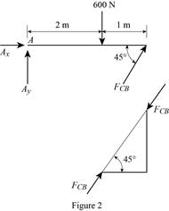
(b)
To identify and draw: The two force members and the free body diagrams of each member of the frame.
Explanation of Solution
Assumptions:
- Consider the state of member as tension where the force is pulling the member and as compression where the force is pushing the member.
- Consider the force indicating right side as positive and left side as negative in horizontal components of forces.
- Consider the force indicating upside is taken as positive and downside as negative in vertical components of forces.
The member CB is a two force member.
Show the free body diagram of the members of the frame as in Figure (2).
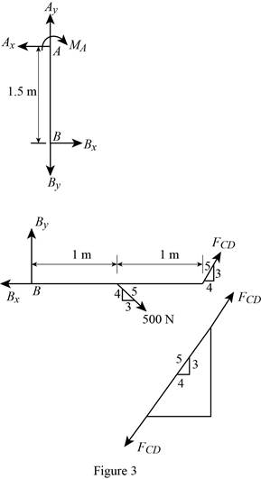
(c)
To identify and draw: The two force members and the free body diagrams of each member of the frame.
Explanation of Solution
Assumptions:
- Consider the state of member as tension where the force is pulling the member and as compression where the force is pushing the member.
- Consider the force indicating right side as positive and left side as negative in horizontal components of forces.
- Consider the force indicating upside is taken as positive and downside as negative in vertical components of forces.
The member CD is a two force member.
Show the free body diagram of the members of the frame as in Figure (3).
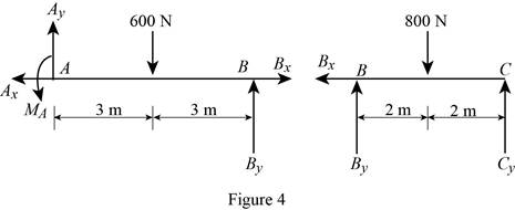
(d)
To identify and draw: The two force members and the free body diagrams of each member of the frame.
Explanation of Solution
Assumptions:
- Consider the state of member as tension where the force is pulling the member and as compression where the force is pushing the member.
- Consider the force indicating right side as positive and left side as negative in horizontal components of forces.
- Consider the force indicating upside is taken as positive and downside as negative in vertical components of forces.
Show the free body diagram of the members of the frame as in Figure (4).
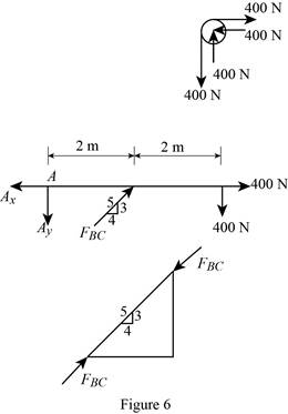
(e)
To identify and draw: The two force members and the free body diagrams of each member of the frame.
Explanation of Solution
Assumptions:
- Consider the state of member as tension where the force is pulling the member and as compression where the force is pushing the member.
- Consider the force indicating right side as positive and left side as negative in horizontal components of forces.
- Consider the force indicating upside is taken as positive and downside as negative in vertical components of forces.
The member BC is a two force member.
Show the free body diagram of the members of the frame as in Figure (5).

(f)
To identify and draw: The two force members and the free body diagrams of each member of the frame.
Explanation of Solution
Assumptions:
- Consider the state of member as tension where the force is pulling the member and as compression where the force is pushing the member.
- Consider the force indicating right side as positive and left side as negative in horizontal components of forces.
- Consider the force indicating upside is taken as positive and downside as negative in vertical components of forces.
The member BC is a two force member.
Show the free body diagram of the members of the frame as in Figure (5).
Want to see more full solutions like this?
Chapter 6 Solutions
INTERNATIONAL EDITION---Engineering Mechanics: Statics, 14th edition (SI unit)
Additional Engineering Textbook Solutions
Mechanics of Materials (10th Edition)
Statics and Mechanics of Materials (5th Edition)
Engineering Mechanics: Dynamics (14th Edition)
Mechanics of Materials
Automotive Technology: Principles, Diagnosis, and Service (5th Edition)
Automotive Technology: Principles, Diagnosis, And Service (6th Edition) (halderman Automotive Series)


- 6-85. The three power lines exert the forces shown on the truss joints, which in turn are pin-connected to the poles AH and EG. Determine the force in the guy cable AI and the pin reaction at the support H. 20 ft D B -40 ft--40 ft- 800 lb 800 lb H 800 lb -50 ft-30 ft--30 20 ft -30 ft-30 ft-30 ft-30 ft 30 ft-30 20 ft ft-50 ft- 125 ftarrow_forward6-11. Determine the force in each member of the Pratt truss, and state if the members are in tension or compression. J 2 m 2 m L H 2 m C E F -2 m--2 m--2 m--2 m---2 m--2 m- 10 kN 10 kN 20 kN Prob. 6-11arrow_forwardProblem 6. •5-5. Draw the free-body diagram of the truss that is supported by the cable AB and pin C. B 30° 2 m 3 kN 4 kN 2 m 2 m 2 m Prob. 5-5arrow_forward
- 6-3. Determine the force in each member of the truss. State if the members are in tension or compression. 3 ft- 3 ft- 3 ft- В F 13, 12 4 ft 4 ft 130 lb E O00 Prob. 6-3arrow_forward6-21. A force of P = 8 lb is applied to the handles of the pliers. Determine the force developed on the smooth bolt B and the reaction that pin A exerts on its attached members. P -5 in. +1.5 in.- 1.25 in. 1.25 in. P Prob. 6-21 A Barrow_forward6-30. Determine the force in members CD, HI, and CH of the truss, and state if the members are in tension or compression. K J I H 4 ft A В F -3 ft 3 ft 3 ft 3 ft 3 ft - 1500 lb 1500 lb 1500 lb 1500 lb 1500 lbarrow_forward
- Determine the horizontal and vertical components of reaction at the pin A and the tension developed in cable BC used to support the steel frame. •5 60 kN m1m 1m 30 kN m 3 m Prob. 5-21arrow_forward6-46. Determine the force developed in members BC and CH of the roof truss and state if the members are in tension or compression. Determine the force in members CD and GF of the truss and state if the members are in tension or compression. Also indicate all zero-force members. 2 kN 1.5 m 0.8 m B A |H G |F E ▼1.5 kN -2 m - -2 m - Probs. 6–46/47 Fec = 3.25 kN (C) Fen= 1.92 kN (T) Answers:arrow_forward6-53 Determine the force exerted by the cable at B and the reaction at support A of the bar shown in Fig. D 20 60° B 800 lb 3 ft 3 ftarrow_forward
- 3-2. The members of a truss are pin connected at joint O. Determine the magnitude of F, and its angle for equilibrium. Set F - 6 KN. 5 kN 70 30 7 KN Probs. 3-1/2arrow_forwardThe 300 kg uniform I-beam supports the 120 kg load. What are the reactions at the supports A and B? 5.6 m - 2.4 m B A 120 kgarrow_forward7-22 Determine the forces in members CD, DI, and HI of the truss shown in Fig. 18 kN 10 kN 14 kN E 3 m B H 3 m A 3 m 3 m 3 m -3 m -3 m 3 m-arrow_forward
 Elements Of ElectromagneticsMechanical EngineeringISBN:9780190698614Author:Sadiku, Matthew N. O.Publisher:Oxford University Press
 Mechanics of Materials (10th Edition)Mechanical EngineeringISBN:9780134319650Author:Russell C. HibbelerPublisher:PEARSON
 Thermodynamics: An Engineering ApproachMechanical EngineeringISBN:9781259822674Author:Yunus A. Cengel Dr., Michael A. BolesPublisher:McGraw-Hill Education
 Control Systems EngineeringMechanical EngineeringISBN:9781118170519Author:Norman S. NisePublisher:WILEY
 Mechanics of Materials (MindTap Course List)Mechanical EngineeringISBN:9781337093347Author:Barry J. Goodno, James M. GerePublisher:Cengage Learning
 Engineering Mechanics: StaticsMechanical EngineeringISBN:9781118807330Author:James L. Meriam, L. G. Kraige, J. N. BoltonPublisher:WILEY