
Concept explainers
Videos
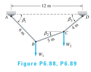
The cable of length 15 m supports the forces
(a)
Derive the simultaneous equations for
Answer to Problem 6.89P
Three simultaneous equations denoted by (a), (b) and (c) are derived.
Explanation of Solution
Given information:
Length of the cable is 15 m.
Forces at B and C are
Calculations:
From geometry:
Apply Eq. (6.19) to joints B and C
Equating two equations:
Conclusion:
Three simultaneous equations relating
(b)
Show that the solution of the equations derived in part (a) are
Answer to Problem 6.89P
Solution of the three equations defined in part (a) are
Explanation of Solution
Given information:
Length of the cable is 15 m.
Forces at B and C are
Equations derived in part (a):
Calculations:
Substituting the values
Conclusion:
Since all three equations are satisfied, thus
(c)
Find the force in each segment in terms of W.
Answer to Problem 6.89P
Force in segment AB:
Force in segment BC:
Force in segment CD:
Explanation of Solution
Given information:
Length of the cable is 15 m.
Forces at B and C are
Equations derived in part (a):
Calculations:
Using Eq. 6.19 to joint B:
Applying Eq. (6.18) to joints B, C and D (note that
Conclusion:
Force in segments AB, BC and CD are
Want to see more full solutions like this?
Chapter 6 Solutions
International Edition---engineering Mechanics: Statics, 4th Edition


- A tie plate is used to transmit three-bar forces to a beam as shown in the figure. The modulus of the resultant R of the three forces is 100 kN. If the force F1 has a modulus of 20 kN, determine the moduli of the forces F2 and F3arrow_forwardFor the bent pipe shown in the figure, it is sought to replace the system of three forces with a single equivalent resultant force R. Find the distance d (in metres) from point O to the point on the x-axis through which the line of action of R passes. a = 379 N, b= 146 N 0.25 m 50 N 0.25 m a b 0.25 m 0.2 m xarrow_forwardone end of the uniform beam of mass 50 kg is hinged to a wall. The other end of the beam is supported by a cable that makes angles e = 30 degrees with both the wall and the beam. A box of mass 10 kg is hanged at the end of the beam with a rope. The magnitude of the forces at the hinge. * Hinge rope M3=10kg cablearrow_forward
- Problem #3: From the given set of non-concurrent forces shown in the figure, determine the Resultant force which could represent them. Figure: Q=20KN IC. T=40KN P=25KN: Im CB W=50KNarrow_forwardSelect the distance a between 2 m and 5 m and the force P between 15 kN and 35 kN in the cage system shown in the figure and find the rod forces. Also note that the forces on the rods did not compress my tension. (AE, AB, BE, DE, CD, BC, BD =?)arrow_forwardThe wheels, axle, and handles of a wheelbarrow weigh W = 55 N. The load chamber and its contents weigh WL = 623 N. The drawing shows these two forces in two different wheelbarrow designs. To support the wheelbarrow in equilibrium, the man’s hands apply a force to the handles that is directed vertically upward. Consider a rotational axis at the point where the tire contacts the ground, directed perpendicular to the plane of the paper. Find the magnitude of the man’s force for both designs.arrow_forward
- Consider the three-dimensional structure shown in the figure, fixed to the ground at point O, and restrained by cables AB and CD. The tension T in the restraining cable CD is 2.7 kN. Calculate the magnitude of the vector moment (in kNm) produced by the force exerted by the cable CD on point C, about the point O (assume use of the right-hand rule). Take a = 4.6 metres, and b = 4.3 metres. b (m) 3 m 4 m а (m) B D*y 4 marrow_forwardAt the top of a steel pole, there are two cables as shown in the figure. It is known that the weight of the pole is vertical and that the force applied horizontally at the top of the pole is 2500 N. If the 2500 N force is parallel to the z-axis (alpha=90), calculate the Tension in each cable (T1-3 and T1-4).arrow_forwardQI/ The rigid pole and cross-arm assembly is supported by the three cables shown. A turnbuckle at D is tightened until it induces a tension T in CD of 1.2 kN. Express T as a vector. Does it make any difference in the result which coordinate system is used? Ans. T = 0.321i + 0.641j – 0.962k kN, 1.5 m /C B 1m 1.5 m T = 1.2 kN 3m E 01.5 m 3 m 2 m marrow_forward
- Q7/ Two integral pulleys are subjected to the belt tensions shown in the figure. If the resultant R of these forces passes through the center O, determine the tension force T and the magnitude of R and the counterclockwise angle e it makes with the x-axis? Ans: T= 60N, R= 193.7N, 0 = 34.7°. %3D 160 N 200 N 30 100 200 mm mm 30 150 Narrow_forwardFind the sum of the horizontal forces in Newton if F1 = 100 N at 30 deg N of E and F2 = 80 N at 45 deg N of W.arrow_forwardCable AB supports the uniformly distributed load of 4 kN/m. If the slope of the cable at A is zero, compute (a) the maximum tensile force in the cable; and (b) the length of the cable B 50 m 4 kN/m Tmax = 250 kN; S = 70 m Tmax = 300 kN; S = 75 m Tmax = 350 kN ; S = 80 m Tmax = 400 kN; S = 85 m 40 m A O Oarrow_forward
 International Edition---engineering Mechanics: St...Mechanical EngineeringISBN:9781305501607Author:Andrew Pytel And Jaan KiusalaasPublisher:CENGAGE L