
Videos
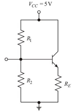
For the circuit in Figure P6.54, the parameters are
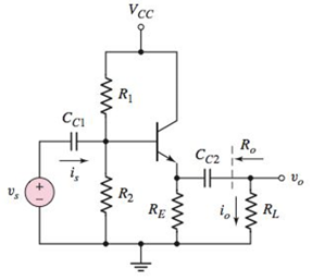
Figure P6.54
(a)
The value of
Answer to Problem 6.54P
The values of resistances are:
Explanation of Solution
Given:
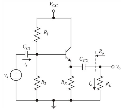
Given circuit:
Given Data:
Calculation:
Considering the BJT (Bipolar Junction Transistor) as single node, then, by Kirchhoff’s current law, the quiescent emitter current
In CE mode:
The quiescent collector current
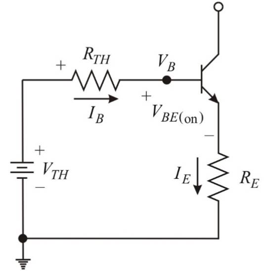
DC analysis of given circuit
(Reducing the ac source

The Thevenin resistance
(Shorting the voltage source)
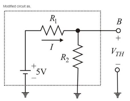
Therefore, the Thevenin voltage from the above circuit,
Using the equation (3),
Modified circuit as,

Applying Kirchhoff’s voltage law around the collector-emitter loop as,
To calculate the value of
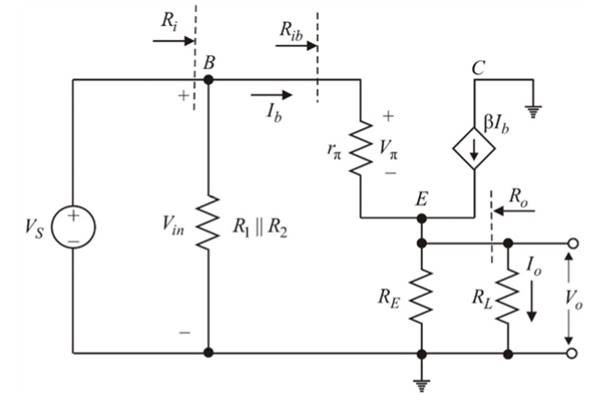
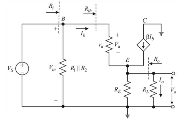
Small-signal analysis of given circuit
(Reducing the dc source to zero and the capacitors to short)
Diffusion resistance
The input resistance
Small signal current gain
Given the small signal current gain
Modified circuit as,

The Thevenin network is shown in above figure and
Kirchhoff's voltage law in the base-emitter loop as,
From equations (5), (8) and (9)
Combining equations (3), (4) and (10)
From equations (3) and (11)
Finding the output resistance
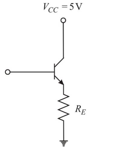
(b)
The current gain.
Answer to Problem 6.54P
The current gain for
Explanation of Solution
Given:
Given circuit:

Given Data:
Calculation:
Considering the BJT (Bipolar Junction Transistor) as single node, then, by Kirchhoff’s current law, the quiescent emitter current
In CE mode:
The quiescent collector current
DC analysis of given circuit
(Reducing the ac source
The Thevenin resistance
(Shorting the voltage source)

Therefore, the Thevenin voltage from the above circuit,
Using equation (3),
Modified circuit as,
Applying Kirchhoff’s voltage law around the collector-emitter loop as,
To calculate the value of
Small-signal analysis of given circuit
(Reducing the dc source to zero and the capacitors to short)
Diffusion resistance
The input resistance
Small signal current gain
Given the small signal current gain
Modified circuit as,
The Thevenin network is shown in above figure and
Kirchhoff's voltage law in the base-emitter loop as,
From equations (5), (8) and (9)
Combining equations (3), (4) and (10)
From equations (3) and (11)
Finding the output resistance
Determining the Small signal current gain
With load resistance
Want to see more full solutions like this?
Chapter 6 Solutions
Microelectronics: Circuit Analysis and Design


- Q6) Design full adder circuit using half adder circuit.arrow_forward100 W at 60 V from a Specify the 2 percent. size. Design a buck-boost converter to supply a load of 30 V source. The output ripple must be no more than duty ratio, switching frequency, inductor size, and capacitorarrow_forwardIn the signal flow graph of the given figure, the number of forward paths is * O 1 4 2arrow_forward
- A circuit consist of two cascaded opamp amplifiers, If the gain of first stage is 6.7 and the gain of the second stage is 3. Then the total voltage gain A, isarrow_forwardDerive the transfer function of the electric circuits for figurearrow_forward1. Build a circuit that allows variable aplification from 1 to 10 time, you can use inverting configurations but the net phase change must be zero. include procedure and values for resistors and input voltage. please use AD620 for amplifiersarrow_forward
- A boost converter is required to have an output voltage of 8 V andsupply a load current of 1 A. The input voltage varies from 2.7 to4.2 V. A control circuit adjusts the duty cycle to keep the outputvoltage constant. If the switching frequency is 200 kHz, determine:i. a value for the inductor such that the variation in inductorcurrent is no more than 40% of the average inductor current forall operating conditions.ii. a value for the capacitor such that the output voltage ripple isno more than 2%.iii. in case the OFF period is reduced by 30% for constantfrequency operation, find the new output voltagearrow_forwardWhat type of A/D converter would work best for video signals with a frequency content up to 5 MHz? Why? (Our subject is Principles of Electronic Communications)arrow_forwardBASIC ELECTRONICS Given Idss = 12mA and Vp= -4V Sketch the drain and transconductance curve for VGS = +2V, +1V, 0V -1V, -2V, -3V and -4Varrow_forward
- 6. An AC precision integrator is desired for a particular application to perform the operation: Vo'(t) = -1200 Vi(t) dt The primes indicate the ac portions of the respective functions. The lowest frequency other than a possible de component of the input signal is estimated to be 1.5 kHz. Determine a suitable design. 7. A low frequency differentiator is desired for a particular application n to perform the operation Vo(t) = -0.002 dvi(t)/ dt Based on a periodic signal with a frequency of 1 kHz, determine a suitable design. 8. Design an astable 555 timer circuit to produce 1kHz square wave, where TH = 0.35 ms and T₁ = 0.65 ms. Select C = 0.01 UE, Determine R₁ and Ra. 9. Design a monostable 555 timer circuit to produce an output pulse 5 ms wide. 10. Using op amps with Xsat = +/- 13 V, design a square/ triangular wave function generator circuit to generate 2 kHz triangular wave with a peak-to-peak voltage of 12 V. 11. Design a non inverting Schmitt trigger circuit with VT to be adjustable…arrow_forwardQ4 (a) The circuit shown in Figure Q4(a) is an oscillator. For this circuit: RF RA R VF R Figure Q4(a) Derive the expression for the feedback network, ß =E Vo (i) (ii) Determine the frequency of oscillation, and (iii) Find the ratio of Rf/RA to ensure the condition for oscillation is fulfilled. Design an astable multivibrator using 555 IC with a frequency of 50 kHz and 75% duty cycle. Label the circuit properly. (b)arrow_forwardFor the signal and circuit of Figure 6, the op-amp has a slew rate of SR=0.75 V/µs. a) Calculate the maximum frequency that may be used. b) Determine if the signal will be an amplified duplicate at the output.arrow_forward
 Introductory Circuit Analysis (13th Edition)Electrical EngineeringISBN:9780133923605Author:Robert L. BoylestadPublisher:PEARSON
 Delmar's Standard Textbook Of ElectricityElectrical EngineeringISBN:9781337900348Author:Stephen L. HermanPublisher:Cengage Learning
 Programmable Logic ControllersElectrical EngineeringISBN:9780073373843Author:Frank D. PetruzellaPublisher:McGraw-Hill Education
 Fundamentals of Electric CircuitsElectrical EngineeringISBN:9780078028229Author:Charles K Alexander, Matthew SadikuPublisher:McGraw-Hill Education
 Electric Circuits. (11th Edition)Electrical EngineeringISBN:9780134746968Author:James W. Nilsson, Susan RiedelPublisher:PEARSON
 Engineering ElectromagneticsElectrical EngineeringISBN:9780078028151Author:Hayt, William H. (william Hart), Jr, BUCK, John A.Publisher:Mcgraw-hill Education,