
Concept explainers
Videos
6-37* to 6-46* For the problem specified in the table, build upon the results of the original problem to determine the minimum factor of safety for fatigue based on infinite life, using the modified Goodman criterion. The shaft rotates at a constant speed, has a constant diameter, and is made from cold-drawn AISI 1018 steel.
| Problem Number | Original Problem, Page Number |
| 6-41* | 3–72, 152 |
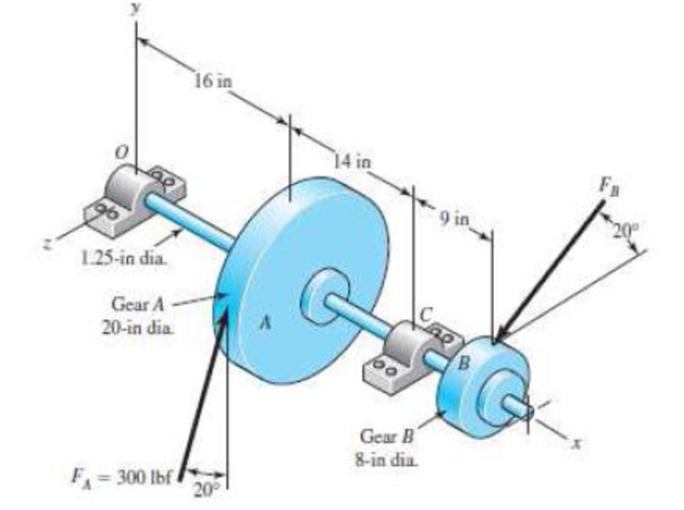
3-72* to 3-73* A gear reduction unit uses the countershaft shown in the figure. Gear A receives power from another gear with the transmitted force FA applied at the 20° pressure angle as shown. The power is transmitted through the shaft and delivered through gear B through a transmitted force FB at the pressure angle shown.
- (a) Determine the force FB assuming the shaft is running at a constant speed.
- (b) Find the bearing reaction forces, assuming the bearings act as simple supports.
- (c) Draw shear-force and bending-moment diagrams for the shaft. If needed, make one set for the horizontal plane and another set for the vertical plane.
- (d) At the point of maximum bending moment, determine the bending stress and the torsional shear stress.
- (e) At the point of maximum bending moment, determine the principal stresses and the maximum shear stress.
The minimum factor of safety for fatigue based on infinite life.
Answer to Problem 41P
The minimum factor of safety for fatigue based on infinite life is
Explanation of Solution
The following figure shows the free body diagram of the gear A.
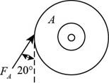
Figure-(1)
The following figure shows the free body diagram of the gear B.
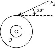
Figure-(2)
Calculate the force
Here, the force acting on pulley
Write the moment about bearing
Here, the reaction force at bearing
Write the equation to balance the forces in
Here, the reaction force at bearing
Write the moment about bearing
Here, the reaction force at bearing
Write the equation to balance the forces in
Here, the reaction force at bearing
Calculate the reaction forces at bearing
Here, the reaction force at bearing
Calculate the reaction forces at bearing
Here, the reaction force at bearing
The calculations for shear force and bending moment diagram in
Calculate the shear force at
Here, the shear force at
Calculate the shear force at
Here, the shear force at
Calculate the shear force at
Here, the shear force at
Calculate the shear force at
Here, the shear force at
Calculate the moment at
Here, the moment at
Calculate the moment at
Here, the moment at
Calculate the moment at
Here, the moment at
Write the net moment at
Here, the net moment at
Write the net moment at
Here, the net moment at
Write the torque transmitted by shaft from
Here, the torque transmitted by shaft from
Calculate the bending stress.
Here, the bending stress is
Calculate the shear stress.
Here, the shear stress is
Calculate the maximum principal stress.
Here, the maximum principal stress is
Calculate the minimum principal stress.
Here, the minimum principal stress is
Calculate the maximum shear stress.
Here, maximum shear stress is
Write the expression for von Mises alternating stress.
Here, the amplitude component of the axial stress is
Write the expression for von Mises mid-range stress.
Here, the mid-range component of the axial stress is
Write the expression for von Mises maximum stress.
Here, the maximum component of the axial stress is
Write the expression for yield factor of safety.
Here, the yield strength of the material is
Write the expression for endurance limit for test specimen.
Here, the minimum tensile strength is
Write the surface factor for the countershaft.
Here, the constants for surface factor are
Write the size factor for the countershaft.
Write the endurance limit at the critical location of the machine part.
Write the modified Goodman equation.
Here, the fatigue factor of safety is
Conclusion:
Substitute
Substitute
Substitute
Substitute
Substitute
Substitute
Substitute
Substitute
Substitute
Substitute
Substitute
Substitute
Substitute
Thus, the shear force and bending moment diagram in
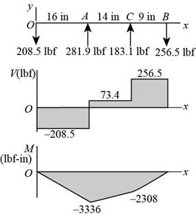
Figure-(3)
Substitute
Substitute
Substitute
Substitute
Substitute
Substitute
Thus, the shear force and bending moment diagram in
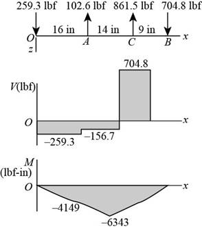
Figure-(4)
Substitute
Substitute
Since,
The critical location is at C.
Substitute
Substitute
Substitute
Substitute
Substitute
Substitute
Substitute
Substitute
Substitute
Refer to the Table A-20 “Deterministic ASTM Minimum Tensile and Yield Strengths for Some Hot-Rolled (HR) and Cold-Drawn (CD) Steels” to obtain the yield strength as
Substitute
Substitute
Refer to Table 6-2 “Parameters for Marin Surface Modification Factor” to obtain
Substitute
Substitute
Substitute
Substitute
Thus, the minimum factor of safety for fatigue based on infinite life is
Want to see more full solutions like this?
Chapter 6 Solutions
Shigley's Mechanical Engineering Design (McGraw-Hill Series in Mechanical Engineering)


- 6-28 The figure shows a formed round-wire cantilever spring subjected to a varying force. The hardness tests made on 50 springs gave a minimum hardness of 400 Brinell. It is apparent from the mounting details that there is no stress concentration. A visual inspection of the springs indicates that the surface finish corresponds closely to a hot- rolled finish. Ignore curvature effects on the bending stress. What number of applica- tions is likely to cause failure? Solve using: (a) Goodman criterion. (b) Gerber criterion. = 40 lbf max 12 in- = 20 lbf min Problem 6-28arrow_forwarda) The rotating step shaft is subjected to the force as shown in the figure. It is supported by bearings at A and F. The shaft is machined using AISI 1040 CD steel. Determine the minimum fatigue factor of safety based on achieving infinite life. If infinite life is not predicted, estimate the number of cycles failure. Also check for yielding. Given Data: (Notch sensitivity (q)=0.8, Sut=85 kpsi, Syield= 71 kpsi, Surface condition modification factor ka=0.879, Size modification factor kb=0.790, Load modification factor kc=1, fatigue fraction (f)=0.867) * In order to determine Kt; Use Figure A-15-9 in your textbook. Dimensions are in inch and all fillet radius:1/14 inch y 860 lbf de 1.75 1.5 1.0 1.0 B V A| D E F 0.5 8 -8.5- R1 R2 -19.5 20arrow_forwardpls find box ur answer Determine the value of the von Mises stress at point A. The von Mises stress at point A is This problem illustrates that the factor of safety for a machine element depends on the particular point selected for analysis. Here you are to compute factors of safety, based upon the distortion-energy theory, for stress elements at A and B of the member shown in the figure. This bar is made of AISI 1006 cold- drawn steel and is loaded by the forces F= 0.55 kN, P = 4 kN, and T = 25 N-m. Given: Sy= 280 MPa. 5 15-mm D. 100 mm- MPa.arrow_forward
- 6-10 A rotating shaft of 25-mm diameter is simply supported by bearing reaction forces R, and R2. The shaft is loaded with a transverse load of 13 kN as shown in the figure. The shaft is made from AISI 1045 hot-rolled steel. The surface has been machined. Determine (a) the minimum static factor of safety based on yielding. (b) the endurance limit, adjusted as necessary with Marin factors. (c) the minimum fatigue factor of safety based on achieving infinite life. (d) If the fatigue factor of safety is less than 1 (hint: it should be for this problem), then estimate the life of the part in number of rotations.arrow_forwardCarbon Steel L=100mm dsmall= 20mm moment of inertia ratio between stepped cross-sectional area = 1:2 F=2500 N at A and a fillet radius at the step of 2mm -loading cycles that the design can withstand before fatigue failure - calculate cycles using goodman line and max stress from static analysis. -determine the effect of the 2mm fillet ratio on the fatigue analyisis. constant force at Aarrow_forward7-5 A rotating step shaft is loaded as shown, where the forces FA and F3 are constant at 600 lbf and 300 lbf. respectively, and the torque T alternates from 0 to 1800 lbf - in. The shaft is to be considered simply supported at points O and C, and is made of AISI 1045 CD steel with a fully corrected endurance limit of S₂ = 40 kpsi. Let Kf = 2.1 and K = 1.7. For a design factor of 2.5 determine the minimal acceptable diameter of section BC using the (a) DE-Gerber criterion. (b) DE-Goodman criterion. n 6 in FA = 600 lbf 6 in FB = 300 lbf 6 in T, n Page 413arrow_forward
- The rotating shaft shown in the figure is machined from AISI 1020 CD steel. It is subjected to a force of F = 6 kN. Find the minimum factor of safety for fatigue based on infinite life. If the life is not infinite, estimate the number of cycles. Be sure to check for yielding. The diameter of the bar is 35 mm and the radius of the step down in the shaft is 3 mm. All dimensions listed below are in mm. 25 D. 20 - 20 -35 D. 180 -3 R. 500- F 280- -175- -50 D. -25 D. -20 20arrow_forwardA solid round bar with diameter of 2 in has a groove cut to a diameter of 1.8 in, with a radius of 0.1 in. The bar is not rotating. The bar is loaded with a repeated bending load that causes the bending moment at the groove to fluctuate between 0 and 25 000 lbf in. The bar is hot-rolled AISI 1095, but the groove has been machined. Determine the factor of safety for fatigue based on infinite life and the factor of safety for yielding. Plars & .arrow_forward1. A rotating l-in diameter solid round bar has a groove 0.1-in deep with a 0.1-radius machined into it. The bar is made of AISI 1020 CD steel and is subjected to a purely reversing torque of 1800 lbf-in. For the S-N curve of the material, let f= 0.9. 1) Estimate the number of cycles to failure. 2) If the bar is also placed in an environment with a temperature of 750 °F, estimate the number of cycles to failure. Note: for pure shear stress state, find ta and Tm to replace oa and om. Apply the load factor k. = 0.59. To get safety factor against first-cycle yielding, use Sgy=0.577 Sy (based on DE theory). For fatigue life or fatigue failure criteria, Replace Sut with Sgu. Ssu = 0.67Sµtarrow_forward
- Requlred Informatlon The shaft shown in the figure is machined from AISI 1040 CD steel. The shaft rotates at 1600 rpm and is supported in rolling bearings at A and B. The appled forces are F = 900 Ibf and F2 = 1350 Ibf. Determine the minimum fatigue factor of safety based on achieving infinite life. If infinite life is not predicted, estimate the number of cycles to fallure. Also check for ylelding. -8 in- -8 in- 8 in F2 17 in in 3 in -10 in- -10 in- in 글 in All fillets in R. B What are the values of the theoretical stress-concentration factor, the notch sensitivity, and the fatigue stress-concentration factor? The value of the theoretical stress concentration-factor Is The value of the notch sensitivity is The value of the fatigue stress concentration-factor Isarrow_forwardThe figure below shows a boat propeller mounted on a drive shaft with a 7 mm diameter (d) cylindrical drive pin inserted through the hub and the shaft. The drive shaft diameter, D, inside the hub is 69 mm. The pin is made from AISI 1020 cold rolled steel, which has a yield stress of 427 MPa and an ultimate stress of 621 MPa. If the drive pin is subjected to an overload (e.g. strikes a log), calculate the torque (Nm) required to shear the pin. Note: Assume that the max shear stress of the pin material is approximately equal 82% of the ultimate tensile stress. Do not include units in your answer. Pin F Hub Drive pin Shaft Drive shaft F Shear planes Hub Answer:arrow_forward2. The rotating shaft shown in the figure is machined from AISI 1020 CD steel. It is subjected to a force of F= 5.7 kN. Find the minimum factor of safety for fatigue based on infinite life. If the life is not infinite, estimate the number of cycles. Be sure to check for yielding. 25 D.- 20- -20 -35 D. -180- -500- -3 R. 280- (units in mm) -175- -50 D. -25 D. -20 -20arrow_forward
 Mechanics of Materials (MindTap Course List)Mechanical EngineeringISBN:9781337093347Author:Barry J. Goodno, James M. GerePublisher:Cengage Learning