
Videos
Obtain an expression for vout as labeled in the circuit of Fig. 6.50 if v1 equals (a) 0 V; (b) 1 V; (c) −5 V; (d) 2 sin 100t V.
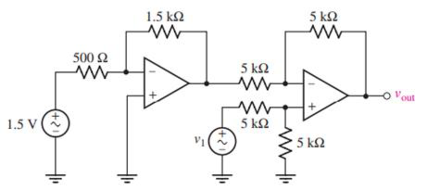
FIGURE 6.50
(a)
Find the output voltage
Answer to Problem 23E
The output voltage
Explanation of Solution
Given data:
The input voltage
Calculation:
The redrawn circuit is shown in Figure 1 as follows.
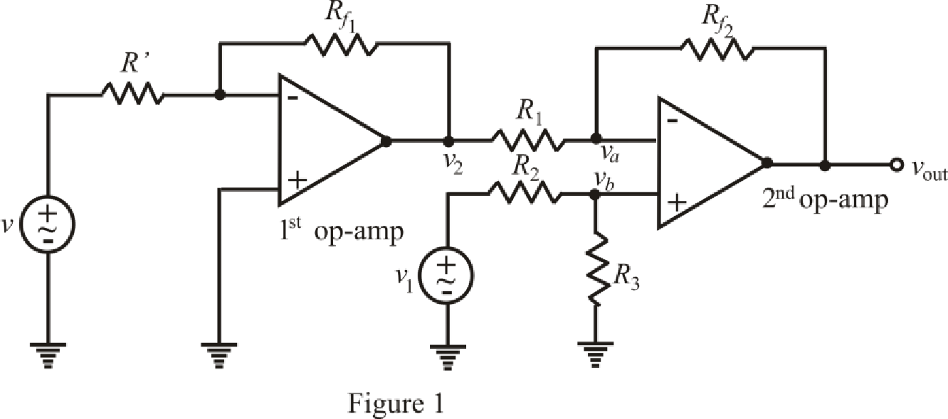
Refer to the Figure 1.
The expression of output voltage for 1st inverting op amp is,
Here,
The expression by the nodal analysis at node
Here,
The expression by the nodal analysis at node
Here,
The expression for the virtual ground concept is as follows,
Refer to the redrawn Figure 1.
Simplify equation (2) as follows.
Rearrange equation (3) for
Substitute
Rearrange for
Substitute for
Substitute
Conclusion:
Thus, the output voltage
(b)
Find the output voltage
Answer to Problem 23E
The output voltage
Explanation of Solution
Given data:
Value of input voltage
Calculation:
Refer to the redrawn Figure 1.
Substitute
Solve for
Conclusion:
Thus, the output voltage
(c)
Find the output voltage
Answer to Problem 23E
The output voltage
Explanation of Solution
Given data:
Value of input voltage
Calculation:
Refer to the redrawn Figure 1.
Substitute
Solve for
Conclusion:
Thus, the output voltage
(d)
Find the output voltage
Answer to Problem 23E
The output voltage
Explanation of Solution
Given data:
Value of input voltage
Calculation:
Refer to the redrawn Figure 1.
Substitute
Solve for
Conclusion:
Thus, the output voltage
Want to see more full solutions like this?
Chapter 6 Solutions
Loose Leaf for Engineering Circuit Analysis Format: Loose-leaf


- Practice Problem Find the voltage across each of the capacitors in Fig. 6.20. 40 pF 60 uF 90 V 20 uF 30 uF Figure 6.20 30 V.arrow_forwardConsider the circuit in Fig. 6.83. Find: (a) Leq, i(t), and i2(t) if i, = in the 20-mH inductor at t = 1 s. 3e' mA, (b) vo(t), (c) energy stored i2 i 4 mH is vo 20 mH 6 mH Leq Figure 6.83 ll ll llarrow_forward6.51 Detemine Leq at terminals a-b of the circuit in Fig. 6.73. 10 mH all 60 mH 25 mH 20 mH a o 30 mH llarrow_forward
- Find the voltage across each of the capacitors in Fig. 6.20. 40 pF 60 aF 90 V 20 uF 30 uF Figure 6.20arrow_forwardSeries and Parallel Capacitors • Example 2: For the circuit in Fig. 6.18, find the voltage across each capacitor. 20 mF 30 mF + 2 - 30 V 40 mF 3 20 mF Figure 6.18arrow_forward6.46 Find vc, i̟, and the energy stored in the capacitor and inductor in the circuit of Fig. 6.69 under dc conditions. 2Ω + 2F ЗА 4Ω 0.5 H 5Ω Figure 6.69 ll wwarrow_forward
- 1. For the op amp circuit shown in Fig. 6.39, calculate vout if (a) R₁ = R₂ = 100 $2 and vin = 5 V; (b) R₂ = 200 R₁ and vin = 1 V; (c) R₁ = 4.7 ks, R₂ = 47 k2, and Vin = 20 sin 5t V. Vin R₁ www R₂ ww + Voutarrow_forward6.48 Under steady-state dc conditions, find i and v in the circuit in Fig. 6.71. 5 mA Figure 6.71 For Prob. 6.48. i 2mH 30 ΚΩ 20 ΚΩ 6 μF Iarrow_forwardPractice Problem 6.5 Under de conditions, find the energy stored in the capacitors in Fig. 6.13. 3 kn Answer: 20.25 mJ, 3.375 mJ. I k2 ww- 30 µF 20 µF = 50 V 6 kN Figure 6.13 For Practice Prob. 6.5.arrow_forward
- Under steady-state de conditions, find i and v in the circuit in e Fig. 6.71. 2 mH el + 5 mA 30 kN 20 k. 6 µFarrow_forwardIn the circuit of Fig. 6.34, i,(1) = 0.6e~" A. If (0) = 1.4 A, find: (a) i,(0); (b) i-(1) and if): (c) v,(f), v(1), and v(f). Practice Problem 6.12 3Harrow_forwardFind vc, iL, and the energy stored in the capacitor and inductor in the circuit of Fig. 6.69 under dc conditions. 2Ω 2 F ЗА 3 A (4 4Ω 0.5 H 5Ω ll Harrow_forward
 Introductory Circuit Analysis (13th Edition)Electrical EngineeringISBN:9780133923605Author:Robert L. BoylestadPublisher:PEARSON
 Delmar's Standard Textbook Of ElectricityElectrical EngineeringISBN:9781337900348Author:Stephen L. HermanPublisher:Cengage Learning
 Programmable Logic ControllersElectrical EngineeringISBN:9780073373843Author:Frank D. PetruzellaPublisher:McGraw-Hill Education
 Fundamentals of Electric CircuitsElectrical EngineeringISBN:9780078028229Author:Charles K Alexander, Matthew SadikuPublisher:McGraw-Hill Education
 Electric Circuits. (11th Edition)Electrical EngineeringISBN:9780134746968Author:James W. Nilsson, Susan RiedelPublisher:PEARSON
 Engineering ElectromagneticsElectrical EngineeringISBN:9780078028151Author:Hayt, William H. (william Hart), Jr, BUCK, John A.Publisher:Mcgraw-hill Education,