
INTERNATIONAL EDITION---Engineering Mechanics: Statics, 14th edition (SI unit)
14th Edition
ISBN: 9780133918922
Author: Russell C. Hibbeler
Publisher: PEARSON
expand_more
expand_more
format_list_bulleted
Videos
Textbook Question
Chapter 5.4, Problem 4CP
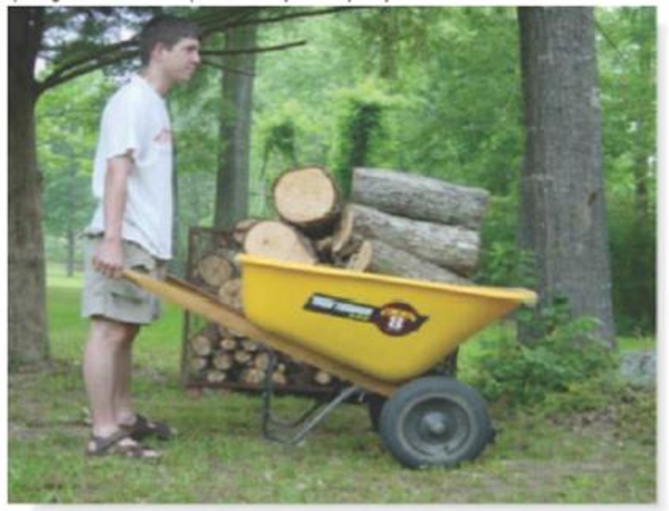
Where is the best place to arrange most of the togs m the wheelbarrow so that it minimizes the amount of force on the backbone of the person transporting the load? Do an equilibrium analysis to explain your answer.
Expert Solution & Answer
Want to see the full answer?
Check out a sample textbook solution
Students have asked these similar questions
2) Where is the best place to arrange most of the logs in the wheelbarrow so that it minimizes the
amount of force on the backbone of the person transporting the load? Do an equilibrium analysis to
explain your answer. Make your own assumptions if necessary.
Where is the best place to arrange most of the logs in the wheelbarrow so that it minimizes the amount of force on the backbone of the person transporting the load? Do an equilibrium analysis to explain your answer.
Where is the best place to arrange most of the logs in thewheelbarrow so that it minimizes the amount of force on the backbone of the person transporting the load? Do an equilibrium analysis to explain your answer. Make your assumptions if necessary.
Chapter 5 Solutions
INTERNATIONAL EDITION---Engineering Mechanics: Statics, 14th edition (SI unit)
Ch. 5.2 - Draw the free-body diagram for the following...Ch. 5.2 - Draw the free-body diagram for the following...Ch. 5.2 - Draw the free-body diagram for the following...Ch. 5.2 - Draw the free-body diagram for the following...Ch. 5.2 - Draw the free-body diagram for the following...Ch. 5.2 - Draw the free-body diagram for the following...Ch. 5.2 - Draw the free-body diagram for the following...Ch. 5.2 - Draw the free-body diagram for the following...Ch. 5.2 - Draw the free-body diagram for the following...Ch. 5.4 - Draw the free body diagram of each object. Prob....
Ch. 5.4 - Determine the horizontal and vertical components...Ch. 5.4 - Determine the horizontal and vertical components...Ch. 5.4 - The truss is supported by a pin at A and a roller...Ch. 5.4 - Determine the components of reaction at the fixed...Ch. 5.4 - The 25 kg bar has a center of mass at G. If it is...Ch. 5.4 - Determine the reactions at the smooth contact...Ch. 5.4 - Determine the components of the support reactions...Ch. 5.4 - Determine the reactions at the supports. Prob....Ch. 5.4 - Determine the horizontal and vertical components...Ch. 5.4 - Determine the reactions at the supports. Prob....Ch. 5.4 - Determine the reactions at the supports. Prob....Ch. 5.4 - Determine the reactions at the supports. Prob....Ch. 5.4 - Determine the tension in the cable and the...Ch. 5.4 - The man attempts to a up port the toad of boards...Ch. 5.4 - Determine the components of reaction at the...Ch. 5.4 - The man has a weight W and stands at the center of...Ch. 5.4 - A uniform glass rod having a length L is placed in...Ch. 5.4 - The uniform rod AB has a mass of 40 kg. Determine...Ch. 5.4 - If the intensity of the distributed load acting on...Ch. 5.4 - If the roller at A and the pin at B can support a...Ch. 5.4 - The relay regulates voltage and current. Determine...Ch. 5.4 - Determine the reactions on the bent rod which is...Ch. 5.4 - The mobile crane is symmetrically supported by two...Ch. 5.4 - Determine the reactions acting on the smooth...Ch. 5.4 - A linear torsional spring deforms such that an...Ch. 5.4 - Determine the force P needed to pull the 50-kg...Ch. 5.4 - Determine the magnitude and direction of the...Ch. 5.4 - The operation of the fuel pump for an automobile...Ch. 5.4 - Determine the magnitude of force at the pin A and...Ch. 5.4 - The dimensions of a jib crane, which is...Ch. 5.4 - The dimensions of a jib crane, which is...Ch. 5.4 - The smooth pipe rests against the opening at the...Ch. 5.4 - The beam of negligible weight is supported...Ch. 5.4 - The cantilevered jib crane is used to support the...Ch. 5.4 - The cantilevered jib crane is used to support the...Ch. 5.4 - The bar of negligible weight is supported by two...Ch. 5.4 - Determine the stiffness k of each spring so that...Ch. 5.4 - The bulk head AD Is subjected to both water and...Ch. 5.4 - The boom supports the two vertical loads. Neglect...Ch. 5.4 - The boom is intended to support two vertical loads...Ch. 5.4 - The 10-kg uniform rod is pinned at end A. If It is...Ch. 5.4 - If the truck and its contents have a mass of 50 kg...Ch. 5.4 - Three uniform books each having a weight W and...Ch. 5.4 - Determine the reactions at the pin A and the...Ch. 5.4 - If rope BC will fail when the tension becomes 50...Ch. 5.4 - The rigid metal strip of negligible weight is used...Ch. 5.4 - The rigid metal strip of negligible weight is used...Ch. 5.4 - The cantilever footing is used to support a wail...Ch. 5.4 - The uniform beam has a weight Wand length l and is...Ch. 5.4 - A boy stands out at the end of the diving board,...Ch. 5.4 - The 30-N uniform rod has a length of l = 1 m. If s...Ch. 5.4 - The uniform rod has a length I and weight W. It is...Ch. 5.4 - I he uniform rod of length L and weight W is...Ch. 5.4 - Assuming that the foundation exerts a linearly...Ch. 5.4 - Assuming that the foundation exerts a linearly...Ch. 5.4 - If it is also subjected to a couple moment of 100...Ch. 5.4 - Determine the distance d for placement of the load...Ch. 5.4 - If d = 1 m, and = 30, determine me normal...Ch. 5.4 - The man attempts to pull the tour wheeler up the...Ch. 5.4 - Where is the best place to arrange most of the...Ch. 5.7 - Draw the free-body diagram of each object.Ch. 5.7 - In each case, write the moment equations about the...Ch. 5.7 - The uniform plate has a weight of 500 lb....Ch. 5.7 - Determine the reactions at the roller support A,...Ch. 5.7 - The rod is supported by smooth journal bearings at...Ch. 5.7 - Determine the support reactions at the smooth...Ch. 5.7 - Determine the force developed in the short link...Ch. 5.7 - Determine the components of reaction that the...Ch. 5.7 - Determine the tension each rope and the force that...Ch. 5.7 - If these components have weights WA = 45000 Wa =...Ch. 5.7 - Determine the components of reaction at the fixed...Ch. 5.7 - Determine the vertical reactions at the wheels C...Ch. 5.7 - Determine the components of reaction at A, the...Ch. 5.7 - Determine the tension in each of the three...Ch. 5.7 - Determine the components of reaction at hinges A...Ch. 5.7 - Determine me tension in each cable and the...Ch. 5.7 - The cables are attached to a smooth collar ring at...Ch. 5.7 - Determine the components of reaction at the...Ch. 5.7 - Determine the components of reaction at the...Ch. 5.7 - Determine the components of reaction at the...Ch. 5.7 - Determine the magnitude of F which will cause the...Ch. 5.7 - Determine the components of reaction at A and the...Ch. 5.7 - Determine the components of reaction at these...Ch. 5.7 - Determine the components or reaction at these...Ch. 5.7 - Compute the x, y, z components of reaction at the...Ch. 5.7 - Determine the magnitude of F2 which will cause the...Ch. 5.7 - At A the connection is with a ball-and-socket....Ch. 5.7 - If it is supported by a ball-and-socket joint at C...Ch. 5.7 - Determine the x, y, z components of reaction at...Ch. 5.7 - Determine the horizontal tension T in the belt on...Ch. 5.7 - Determine the horizontal tension T in the belt on...Ch. 5.7 - Determine the components of reaction at A and the...Ch. 5.7 - If the roller at 8 can sustain a maximum load of 3...Ch. 5.7 - Determine the reactions at the supports A and B...Ch. 5.7 - Determine the normal reaction at the roller A and...Ch. 5.7 - Determine the horizontal and vertical components...Ch. 5.7 - Determine the x, y, z components of reaction at...Ch. 5.7 - Determine the horizontal equilibrium force P that...Ch. 5.7 - Determine the x, y, z components of reaction at...Ch. 5.7 - Determine the x and z components of reaction at...
Knowledge Booster


Learn more about
Need a deep-dive on the concept behind this application? Look no further. Learn more about this topic, mechanical-engineering and related others by exploring similar questions and additional content below.Similar questions
- The bar ABC is supported by three identical, ideal springs. Note that the springs are always vertical because the collars to which they are attached are free to slide on the horizontal rail. Find the angle at equilibrium if W = kL. Neglect the weight of the bar.arrow_forwardWhere is the best place to arrange most of the logs in the wheel barrow so that is minimizes the amaount force on the backbone of the person transporting the load? Do an equilibrium analysis to explain your answer. Make your own assumptions if necessary.arrow_forwardFor Probs. 1-3, (a) draw the free-body diagrams for the entire assembly (or structure) and each of its parts. Neglect friction and the weights of the members unless specified otherwise. Be sure to indicate all relevant dimensions. For each problem, (b) determine the total number of unknown forces and the total number of independent equilibrium equations. Problem 1 500 N 500 N 1 m 500 N (b) (c) Figure 1 Problem 2 -- Ift 4 ft -1.8 ft 100 lb F1.8 ft - 100 lb 100 lb (а) (b) (c)arrow_forward
- Show how to find the force needed to move the top block. Use reasonable data and use an equilibrium analysis to explain your answer.arrow_forwardProblem 3 - Determine whether the block shown is in equilibrium. Find the magnitude and direction of the friction force. Ms=0.30 MK=0.20 400 N 300N 130 45°arrow_forwardQuestion 4 A body of weight 38 N is lying on not a smooth plane inclined at an angle of 31° with the parallel. It is reinforced by an effort (P) parallel to the plane as shown in figure. If the angle of friction is 20°, Calculate the range of force P for which the block can be in equilibrium is. (X,XX,XXX represents the last digits number pf your IC) Theta -31 P Carrow_forward
- Problem 1: The surface of the inclined plane is smooth (no friction). The inclination is 0, with sin0 = h/L, where h is the height of the right end, and L is length of the plane. A box called G (note this is not the weight) is lying on the surface with a pulley system shown in the figure. The mass of the box is m. The box is in equilibrium. (1) Plot the free body diagram for the box G %3D . Calculate the magnitudes for the 3 forces. (T (2) Calculate the force F that is required for the system to remain in equilibrium. es=arrow_forwardDevelop a free body diagram based on the structure. There must be a system FBD and an FBD of one multi-force member.arrow_forwardShow the complete free body diagram for the problem.arrow_forward
- The load on the truss is L=7.2 kN. What is the force in rod AC?arrow_forwardProblem Statement Based on Problem 6-64 from the textbook. Determine the force P required to hold the mass, m, in equilibrium. m= M= 46 kg A P Barrow_forwardNeed help. Please solve this and clearly state how you got your numbers and what formulas you used to solve it. Please make sure you find all the 6 unknows please. Knowing the beta equals 30° and the solid plate weigh 100 kg. What is the cable tension T and the reaction forces at the two bearings? Assume bearing A is a thrust bearing but bearing B is notplease solve for the X component at bearing B. Again please also make you find all the 6 unknows please. And clearly indicate which is which. And please label and make sure to put unitsarrow_forward
arrow_back_ios
SEE MORE QUESTIONS
arrow_forward_ios
Recommended textbooks for you
 International Edition---engineering Mechanics: St...Mechanical EngineeringISBN:9781305501607Author:Andrew Pytel And Jaan KiusalaasPublisher:CENGAGE L
International Edition---engineering Mechanics: St...
Mechanical Engineering
ISBN:9781305501607
Author:Andrew Pytel And Jaan Kiusalaas
Publisher:CENGAGE L
BEARINGS BASICS and Bearing Life for Mechanical Design in 10 Minutes!; Author: Less Boring Lectures;https://www.youtube.com/watch?v=aU4CVZo3wgk;License: Standard Youtube License