Concept explainers
The voltages between the points
Explanation of Solution
Given:
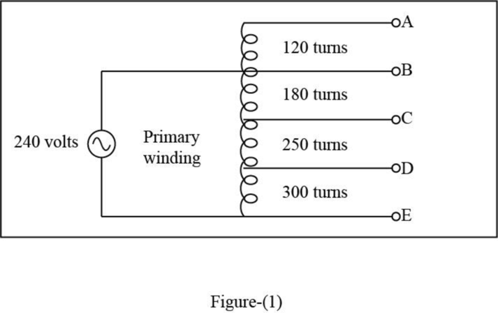
The number of turns between the windings
The number of turns between the windings
The number of turns between the windings
The number of turns between the windings
The voltage connected across windings
The below figure represents the autotransformer windings.
Calculation:
Calculate the voltage per unit turns
Calculate the voltage between the windings
Calculate the voltage between the windings
Calculate the voltage between the windings
Calculate the voltage between the windings
Calculate the voltage between the windings
Calculate the voltage between the windings
Calculate the voltage between the windings
Calculate the voltage between the windings
Calculate the voltage between the windings
Calculate the voltage between the windings
Thus, the voltages between the windings
Want to see more full solutions like this?
Chapter 5 Solutions
Electrical Transformers and Rotating Machines


- Refer to the transformer shown in Figure 5-13 to answer the following questions. What is the turns ratio of the winding between points B and E as compared to the winding between points D and E? Figure 5-13 Autotransformer practice problems.arrow_forwardPlease answer 3 and 4. Use the following data as the basis: a = 4 b = 8 c = 4 d = 7 e = 2 f = 2arrow_forwardWhat is the total current from the voltage source in Figure 6-64 for each switch position? Figure 6-64 15 V + +₁₁ +₁ R₁ 1.0 ΚΩ +₁ R₂ 1.8 ΚΩ www +₁₁ R3 2.2 ΚΩ www R4 2.7 ΚΩarrow_forward
- The figure below shows a four- bar linkage. If a=5m, b=7m, c=9m, d=10m, 0=60°, O-10°, a=30° and w2=1rad/s. (The figure is not to scale) Find the minimum transmission angle in degrees Find the maximum transmission angle in degrees Find toggle angle in degreesarrow_forwardin a dc machine 72 number of coils are used. Find the number of commutator ?segments required 74 72 37 36arrow_forward(a) Explain the meaning of spring force and the graph of spring force against position (b) The 8735 kg helicopter is takes off vertically with its rotor exerting a constant upwardthrust of 117 kN. Determine how far it has risen if its velocity is 11 m/s. In Figure 4 (c), the 30 N block is moving up the smooth inclined surface at velocity and constant force of 2 m/s and 15 N, respectively. (i). Draw the kinetic diagram of all forces exerted on box (ii). Calculate the velocity of the block when it has moved 1 m up the surface from its present position. (c)arrow_forward
- value of (m) = 9 value of (e) = 9 value of (ω) = 9 Value of LL = 9 Value of LR = 10arrow_forwardii) Calculate Vị and V2 (Give the answer in 2 decimal points). V = V2 :arrow_forwardFollowing the procedure discussed in Chapter 7, place wire numbers on the schematic in Figure 8–7. Place corresponding wire numbers on the components shown in Figure 8–8.arrow_forward
- Given a fourbar linkage with the link lengths L1 d 100 mm, L2= a 50 mm, L3= b = 120 mm, L4c-80 mm. For 0₂= 35° and wą - 31 rad/sec (ccw). Find the angle of VBA in degrees to 2 decimal places for the open circuit of the linkage, given s -12.71° and 04-43.51°. Write your angle as a positive number with respect to the x-axis. VBA is the velocity of B with respect to A. This is a general diagram for a fourbar linkage. Not to scale. 032 3 B Open Crossedarrow_forwardThe mechanism used in a marine engine consists of a single crank AB and two connecting rods BC and BD as shown in (Figure 1). Assume r = 0.2 m Part A Determine the magnitude of the velocity of the piston at D the instant the crank is in the position shown and has an angular velocity of w 4 rad/s. Express your answer with the appropriate units. НА VD = Value Units Submit Request Answer Part B Determine the direction of the velocity of the piston at D the instant the crank is in the position shown and has an angular velocity of w = 4 rad/s. Oup and to the left Figure <1 of 1 O down and to the right Submit Request Answerarrow_forwarda=281 b= 208 c= 561 L= 994 P= 867arrow_forward
 Electrical Transformers and Rotating MachinesMechanical EngineeringISBN:9781305494817Author:Stephen L. HermanPublisher:Cengage Learning
 Understanding Motor ControlsMechanical EngineeringISBN:9781337798686Author:Stephen L. HermanPublisher:Delmar Cengage Learning
 Refrigeration and Air Conditioning Technology (Mi...Mechanical EngineeringISBN:9781305578296Author:John Tomczyk, Eugene Silberstein, Bill Whitman, Bill JohnsonPublisher:Cengage Learning