
Engineering Mechanics: Statics & Dynamics (14th Edition)
14th Edition
ISBN: 9780133915426
Author: Russell C. Hibbeler
Publisher: PEARSON
expand_more
expand_more
format_list_bulleted
Videos
Textbook Question
Chapter 4.4, Problem 22P
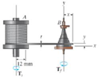
Old clocks were constructed using a fusee B to drive the gears and watch hands. The purpose of the fusee is to increase the leverage developed by the mainspring A as it uncoils and thereby loses some of its tension. The mainspring can develop a torque (moment) Ts = kθ, where k = 0.015 N · m/rad is the torsional stiffness and θ is the angle of twist of the spring in radians If the torque Tf developed by the fusee is to remain constant as the mainspring winds down, and x = 10 mm when θ = 4 rad, determine the required radius of the fusee when θ = 3 rad.
Prob.4-22
Expert Solution & Answer
Want to see the full answer?
Check out a sample textbook solution
Students have asked these similar questions
The ideal spring of constant k=2.6kN/m is attached to the fitted at point A and the end fitted at point B, as shown. The spring is unstretched when theta(A) and theta(B) are both zero. If the fitted is rotated 15⁰ clockwise and the end fitting is rotated 30⁰ counterclockwise, determine the vector expression for the spring force F.
Determine distance C so that the moment the spring force makes about the Z axis is equal to 10.82 N.m
Question 2:
The ideal spring of constant k-2.6 kN/m is attached to the disk at point A and the end fitting at point
B, as shown. The spring is unstretched when OA and Oв are both zero. If the disk is rotated 15° clockwise
and the end fitting is rotated 30°counterclockwise, determine the vector expression for the spring force
F.
Determine distance C so that the moment the spring force makes about the Z axis is equal to 10.82
N.m.
-
A = 15°1
A
250 mm
lllllll
900 mm k = 2.6 kN/m
OB = 30°
B
G
200 mm
The gear and attached V-belt pulley are turning
counterclockwise and are subjected to the tooth load
of 1600 N and the 800-N and 450-N tensions in the
V-belt. Represent the action of these three forces by
a resultant force R at O and a couple of magnitude
M. Is the unit slowing down or speeding up?
15°
280
150
mm
mm
450 N
X
30°
800 N
15°
20°
1600 N
Chapter 4 Solutions
Engineering Mechanics: Statics & Dynamics (14th Edition)
Ch. 4.4 - In each case, determine the moment of the force...Ch. 4.4 - In each case, set up the determinant to find the...Ch. 4.4 - Determine the moment of the force about point O.Ch. 4.4 - Determine the moment of the force about point O.Ch. 4.4 - Determine the moment of the force about point O.Ch. 4.4 - Determine the moment of the force about point O....Ch. 4.4 - Determine the moment of the force about point O.Ch. 4.4 - Determine the moment of the force about point O.Ch. 4.4 - Determine the resultant moment produced by the...Ch. 4.4 - Determine the resultant moment produced by the...
Ch. 4.4 - Determine the resultant moment produced by the...Ch. 4.4 - Determine the moment of force F about point O....Ch. 4.4 - Prob. 11FPCh. 4.4 - Prob. 12FPCh. 4.4 - Prob. 1PCh. 4.4 - Prove the triple scalar product identity A (B C)...Ch. 4.4 - Prob. 3PCh. 4.4 - Prob. 4PCh. 4.4 - Determine the moment about point B of each of the...Ch. 4.4 - The crowbar is subjected to a vertical force of P...Ch. 4.4 - Determine the moment of each of the three forces...Ch. 4.4 - Determine the moment of each of the three forces...Ch. 4.4 - Determine the moment of each force about the bolt...Ch. 4.4 - If FB = 30 lb and FC = 45 lb, determine the...Ch. 4.4 - Prob. 11PCh. 4.4 - The towline exerts a force of P = 6 kN at the end...Ch. 4.4 - Prob. 13PCh. 4.4 - The 20-N horizontal force acts on the handle of...Ch. 4.4 - Two men exert forces of F = 80 lb and P = 50 lb on...Ch. 4.4 - Prob. 16PCh. 4.4 - Prob. 17PCh. 4.4 - The tongs are used to grip the ends of the...Ch. 4.4 - Prob. 19PCh. 4.4 - The handle of the hammer is subjected to the force...Ch. 4.4 - In order to pull out the nail at B, the force F...Ch. 4.4 - Old clocks were constructed using a fusee B to...Ch. 4.4 - The tower crane is used to hoist the 2-Mg load...Ch. 4.4 - The tower crane is used to hoist a 2-Mg load...Ch. 4.4 - If the 1500-lb boom AB, the 200-lb cage BCD, and...Ch. 4.4 - If the 1500-lb boom AB, the 200-lb cage BCD, and...Ch. 4.4 - Determine the moment of the force F about point O....Ch. 4.4 - Determine the moment of the force F about point P....Ch. 4.4 - The force F = {400i 100j 700k} lb acts at the...Ch. 4.4 - The force F = {400i 100j 700k} lb acts at the end...Ch. 4.4 - Determine the moment of the force F about point P....Ch. 4.4 - The pipe assembly is subjected to the force of F =...Ch. 4.4 - The pipe assembly is subjected to the force of F =...Ch. 4.4 - Determine the moment of the force of F = 600 N...Ch. 4.4 - Determine the smallest force F that must be...Ch. 4.4 - Determine the coordinate direction angles , , of...Ch. 4.4 - Determine the moment of force F about point O. The...Ch. 4.4 - Determine the moment of the force F about the door...Ch. 4.4 - Determine the moment of the force F about the door...Ch. 4.4 - Determine the smallest force F that must be...Ch. 4.4 - Prob. 41PCh. 4.4 - A 20-N horizontal force is applied perpendicular...Ch. 4.4 - Prob. 43PCh. 4.4 - The pipe assembly is subjected to the 80-N force....Ch. 4.4 - Prob. 45PCh. 4.4 - Prob. 46PCh. 4.4 - Prob. 47PCh. 4.4 - Prob. 48PCh. 4.4 - Prob. 49PCh. 4.4 - Prob. 50PCh. 4.4 - Using a ring collar, the 75-N force can act in the...Ch. 4.5 - In each case, determine the resultant moment of...Ch. 4.5 - Prob. 4PPCh. 4.5 - Prob. 13FPCh. 4.5 - Prob. 14FPCh. 4.5 - Determine the magnitude of the moment of the 200-N...Ch. 4.5 - Determine the magnitude of the moment of the force...Ch. 4.5 - Prob. 17FPCh. 4.5 - Determine the moment of force F about the x, the...Ch. 4.5 - The lug nut on the wheel of the automobile is to...Ch. 4.5 - Solve Prob. 4-52 if the cheater pipe AB is slipped...Ch. 4.5 - The A-frame is being hoisted into an upright...Ch. 4.5 - Prob. 55PCh. 4.5 - Determine the magnitude of the moments of the...Ch. 4.5 - Determine the moment of this force F about an axis...Ch. 4.5 - Prob. 58PCh. 4.5 - Prob. 59PCh. 4.5 - Prob. 60PCh. 4.5 - Determine the magnitude of the moment of the force...Ch. 4.5 - Determine the magnitude of the moment of the force...Ch. 4.5 - Determine the magnitude of the moment of the force...Ch. 4.5 - A horizontal force of F = {50i} N is applied...Ch. 4.5 - Prob. 65PCh. 4.5 - Prob. 66PCh. 4.6 - Determine the resultant couple moment acting on...Ch. 4.6 - Determine the resultant couple moment acting on...Ch. 4.6 - Prob. 21FPCh. 4.6 - Determine the couple moment acting on the beam.Ch. 4.6 - Determine the resultant couple moment acting on...Ch. 4.6 - Determine the couple moment acting on the pipe...Ch. 4.6 - Prob. 67PCh. 4.6 - Prob. 68PCh. 4.6 - If the resultant couple of the three couples...Ch. 4.6 - Two couples act on the beam. If F = 125 lb,...Ch. 4.6 - Two couples act on the beam. Determine the...Ch. 4.6 - Determine the magnitude of the couple forces F so...Ch. 4.6 - Prob. 73PCh. 4.6 - Prob. 74PCh. 4.6 - Prob. 75PCh. 4.6 - Determine the magnitude of F so that the resultant...Ch. 4.6 - Prob. 77PCh. 4.6 - Prob. 78PCh. 4.6 - Two couples act on the frame. If the resultant...Ch. 4.6 - Prob. 80PCh. 4.6 - Two couples act on the frame. If d = 4 ft,...Ch. 4.6 - Prob. 82PCh. 4.6 - If M1 = 180 lb ft, M2 = 90 lb ft, and M3 = 120...Ch. 4.6 - Prob. 84PCh. 4.6 - The gears are subjected to the couple moments...Ch. 4.6 - Determine the required magnitude of the couple...Ch. 4.6 - Determine the resultant couple moment of the two...Ch. 4.6 - Express the moment of the couple acting on the...Ch. 4.6 - In order to turn over the frame, a couple moment...Ch. 4.6 - Express the moment of the couple acting on the...Ch. 4.6 - If the couple moment acting on the pipe has a...Ch. 4.6 - If F = 80 N, determine the magnitude and...Ch. 4.6 - If the magnitude of the couple moment acting on...Ch. 4.6 - Express the moment of the couple acting on the rod...Ch. 4.6 - If F1 = 100 N, F2 = 120 N, and F3 = 80 N,...Ch. 4.6 - Prob. 96PCh. 4.7 - In each case, determine the x and y components of...Ch. 4.7 - F-25. Replace the leading system by an equivalent...Ch. 4.7 - F-26. Replace the loading system by an equivalent...Ch. 4.7 - Prob. 27FPCh. 4.7 - Prob. 28FPCh. 4.7 - Prob. 29FPCh. 4.7 - F-30. Replace the loading system by an equivalent...Ch. 4.7 - Replace the force system by an equivalent...Ch. 4.7 - Prob. 98PCh. 4.7 - Prob. 99PCh. 4.7 - Prob. 100PCh. 4.7 - Replace the loading system acting on the beam by...Ch. 4.7 - Prob. 102PCh. 4.7 - Prob. 103PCh. 4.7 - Prob. 104PCh. 4.7 - Replace the force system acting on the frame by an...Ch. 4.7 - Prob. 106PCh. 4.7 - Prob. 107PCh. 4.7 - Replace the force system by an equivalent...Ch. 4.7 - Prob. 109PCh. 4.7 - Prob. 110PCh. 4.7 - Prob. 111PCh. 4.7 - Prob. 112PCh. 4.8 - In each case, determine the x and y components of...Ch. 4.8 - Prob. 7PPCh. 4.8 - Replace the loading system by an equivalent...Ch. 4.8 - Prob. 32FPCh. 4.8 - Prob. 33FPCh. 4.8 - Prob. 34FPCh. 4.8 - Prob. 35FPCh. 4.8 - Prob. 36FPCh. 4.8 - Prob. 113PCh. 4.8 - Prob. 114PCh. 4.8 - Prob. 115PCh. 4.8 - Prob. 116PCh. 4.8 - Replace the loading acting on the beam by a single...Ch. 4.8 - Prob. 118PCh. 4.8 - Prob. 119PCh. 4.8 - Prob. 120PCh. 4.8 - Prob. 121PCh. 4.8 - Prob. 122PCh. 4.8 - Prob. 123PCh. 4.8 - Prob. 124PCh. 4.8 - Prob. 125PCh. 4.8 - Replace the force and couple system acting on the...Ch. 4.8 - If FA = 7 kN and FB = 5 kN, represent the force...Ch. 4.8 - Determine the magnitudes of FA and FB so that the...Ch. 4.8 - Prob. 129PCh. 4.8 - Prob. 130PCh. 4.8 - Prob. 131PCh. 4.8 - If FA= 40 kN and FB = 35 kN, determine the...Ch. 4.8 - If the resultant force is required to act at the...Ch. 4.8 - Prob. 134PCh. 4.8 - Replace the force system by a wrench and specify...Ch. 4.8 - Prob. 136PCh. 4.8 - Replace the three forces acting on the plate by a...Ch. 4.9 - Determine the resultant force and specify where it...Ch. 4.9 - Prob. 38FPCh. 4.9 - Prob. 39FPCh. 4.9 - Determine the resultant force and specify where it...Ch. 4.9 - Prob. 41FPCh. 4.9 - Prob. 42FPCh. 4.9 - Replace the loading by an equivalent resultant...Ch. 4.9 - Replace the distributed loading with an equivalent...Ch. 4.9 - Prob. 140PCh. 4.9 - Prob. 141PCh. 4.9 - Replace the distributed loading by an equivalent...Ch. 4.9 - Replace this loading by an equivalent resultant...Ch. 4.9 - The distribution of soil loading on the bottom of...Ch. 4.9 - Replace the loading by an equivalent resultant...Ch. 4.9 - Replace the distributed loading by an equivalent...Ch. 4.9 - Prob. 147PCh. 4.9 - Prob. 148PCh. 4.9 - If the soil exerts a trapezoidal distribution of...Ch. 4.9 - Prob. 150PCh. 4.9 - Prob. 151PCh. 4.9 - Prob. 152PCh. 4.9 - Replace the leading by a single resultant force,...Ch. 4.9 - Prob. 154PCh. 4.9 - Replace the distributed loading by an equivalent...Ch. 4.9 - Prob. 156PCh. 4.9 - Prob. 157PCh. 4.9 - Prob. 158PCh. 4.9 - The distributed load acts on the shaft as shown....Ch. 4.9 - Replace the distributed loading with an equivalent...Ch. 4.9 - Prob. 161PCh. 4.9 - Prob. 162PCh. 4.9 - Prob. 1RPCh. 4.9 - Replace the force F having a magnitude of F = 50...Ch. 4.9 - Prob. 3RPCh. 4.9 - Prob. 4RPCh. 4.9 - Prob. 5RPCh. 4.9 - Prob. 6RPCh. 4.9 - Prob. 7RPCh. 4.9 - Prob. 8RP
Knowledge Booster


Learn more about
Need a deep-dive on the concept behind this application? Look no further. Learn more about this topic, mechanical-engineering and related others by exploring similar questions and additional content below.Similar questions
- When a 6 kg load is hung at point O and member AO is adjusted until it is horizontal, the angle is measured to be 35 Determine the final readings of spring scales S_{1} and S_{a} and solve for the moments they produce about each of the axes passing through A and B if member AB is measured to be 38 cm.arrow_forwardThe disk has a weight of 10 lb and is subjected to a vertical force P 6 lb and a couple moment M = 8 lb ft. The spring is originally unstretched. (Figure 1) Figure 1 of 1 k = 12 lb/ft 1.5 ft M Part A Determine the disk's rotation if the end of the spring wraps around the periphery of the disk as the disk turns. Express your answer using three significant figures. τΫΠΙ ΑΣΦ | ↓↑ vec ? Request Answer Next > 0 = Submit Provide Feedback Oarrow_forwardQ: The door is held open by means of two chain. if the tension in AB and CD is FA= 300N and Fc= 250 N, find the components of force FA. * 1.5m 2.5 m \Fc= 250 N A F= 300 N 30 D 0.5 m B FA= 280j - 93k FA= 285j - 93k FA= 280j - 92karrow_forward
- 4. The gear and attached V-belt pulley are turning counter-dockwise and are subjected to the tooth load of 1600 N and the 800 N and 450 N tensions in the V-belt. Represent the action of these three forces by a resultant force R at O and a couple of magnitude M. Is the unit slowing down or speeding up? 15° 280 mm 150 mm 450 N 30° 800 N 15° 20 1600 Narrow_forward1. Notice the rectangle in the image below. Determine the torque of the forces F, F2, F3, F4, and F, about the shaft through: а. О b. A F 4 m 4 m 3 m F, 3 m F, Please with step by steparrow_forwardThe lift is holding a 190 lb weight as shown. The weight of the horizontal bar is 20 lbs and the weight of the vertical bar is 30 lbs. Calculate the reaction force components and reaction moments at point D? Ignore the radius of the frictionless pulleys. Dimensions: a = 3 ft b = 7 ft B AQ W c = 4 ft d = 6 in d с a b Tension in the rope = Reaction Moment at D = Horizontal reaction force = [ Vertical reaction force = lbs e = 2 ft a = 45° C D E 0 = 20° ft lbs (Click to select) V lbs (Click to select) lbs (Click to select)arrow_forward
- Two beams are joined end to end and hinged at the left end. The left beam has a mass of 10 kg and the right beam has a mass of 12.2 kg. Determine the magnitude of the gravitational torque about the hinge. Use g = 10 N/kg. Enter units as Nm. Hint: You can either determine the center of mass of the combined object and exert the total gravitational torque from there or you can treat each beam individually and add the torques of each.arrow_forwardThe device shown is a part of an automobile seat-back-release mechanism. The part is subjected to the 4.1-N force exerted at A and a 250-N-mm restoring moment exerted by a hidden torsional spring. Determine the y-intercept of the line of action of the single equivalent force. Your answer will be positive if the intercept is above O and negative if below O. F = 4.1 N 18 mm 16° 31 mm 250 N-mm Answer: y = mmarrow_forward2/122 A moment (torque) M applied to the shaft and at- tached arm causes a tension 7 of 120 lb applied to A by the restraining cable AB. Determine the mo- ment Mo of the tension about point O. 16" 14" C 14" M 60° B Problem 2/122 A T= 120 lbarrow_forward
- The spring ABC has a stiffness of 500N/m and an unstretched length of 6m. Calculate the horizontal force, F applied to the cord which is attached at B so that the displacement of the pulley from the wall is d= 1.5m. A k = 500 N/m 6 m F k = 500 N/m Fig. Q3 Force equation: Force equation 3D Moment 3D Cosine rule R - 4 +B-2AB cos e F- Fi+Fj+Fk Ff = F +F +F moment about a point M-rxF Sine rule F| di+dj+dk F F3 Fc sin 4 sin B sinC moment about an axis M=rF Force resultant R-R R +R R. 8= tan Rarrow_forwardThe throttle-control lever OA rotates in the range 0 ≤ 0 ≤ 90°. An internal torsional return spring exerts a restoring moment about O given by M = K(0+1/4), where K = 490 N-mm/rad and is in radians. Determine and plot as a function of the tension Trequired to make the net moment about Ozero. The effects of the radius of the pulley at Bare negligible. After you have completed the plot. answer the questions. Assumer = 65 mm, d = 145 mm. B 45° Answers: If 8 = 25% the tension T = i If 8 = 48°, the tension T= i If 8 = 60%, the tension T= i ZZZ N Narrow_forwardDetermine the spring constant k4 (N/m) if the extension of the whole system is 1.44 m when a force of 29.86 N is applied. Use k1 - 12.67 N/m, k2 - 11.1 N/m, k3 - 28.39 N/m, and k5 - 33.91 N/m. (Use 2 decimal places for the final answer.) k k3arrow_forward
arrow_back_ios
SEE MORE QUESTIONS
arrow_forward_ios
Recommended textbooks for you
 Elements Of ElectromagneticsMechanical EngineeringISBN:9780190698614Author:Sadiku, Matthew N. O.Publisher:Oxford University Press
 Mechanics of Materials (10th Edition)Mechanical EngineeringISBN:9780134319650Author:Russell C. HibbelerPublisher:PEARSON
 Thermodynamics: An Engineering ApproachMechanical EngineeringISBN:9781259822674Author:Yunus A. Cengel Dr., Michael A. BolesPublisher:McGraw-Hill Education
 Control Systems EngineeringMechanical EngineeringISBN:9781118170519Author:Norman S. NisePublisher:WILEY
 Mechanics of Materials (MindTap Course List)Mechanical EngineeringISBN:9781337093347Author:Barry J. Goodno, James M. GerePublisher:Cengage Learning
 Engineering Mechanics: StaticsMechanical EngineeringISBN:9781118807330Author:James L. Meriam, L. G. Kraige, J. N. BoltonPublisher:WILEY
Elements Of Electromagnetics
Mechanical Engineering
ISBN:9780190698614
Author:Sadiku, Matthew N. O.
Publisher:Oxford University Press
Mechanics of Materials (10th Edition)
Mechanical Engineering
ISBN:9780134319650
Author:Russell C. Hibbeler
Publisher:PEARSON
Thermodynamics: An Engineering Approach
Mechanical Engineering
ISBN:9781259822674
Author:Yunus A. Cengel Dr., Michael A. Boles
Publisher:McGraw-Hill Education
Control Systems Engineering
Mechanical Engineering
ISBN:9781118170519
Author:Norman S. Nise
Publisher:WILEY
Mechanics of Materials (MindTap Course List)
Mechanical Engineering
ISBN:9781337093347
Author:Barry J. Goodno, James M. Gere
Publisher:Cengage Learning
Engineering Mechanics: Statics
Mechanical Engineering
ISBN:9781118807330
Author:James L. Meriam, L. G. Kraige, J. N. Bolton
Publisher:WILEY
Mechanics of Materials Lecture: Beam Design; Author: UWMC Engineering;https://www.youtube.com/watch?v=-wVs5pvQPm4;License: Standard Youtube License