
Mechanics of Materials (10th Edition)
10th Edition
ISBN: 9780134319650
Author: Russell C. Hibbeler
Publisher: PEARSON
expand_more
expand_more
format_list_bulleted
Concept explainers
Videos
Textbook Question
Chapter 3.7, Problem 3.34P
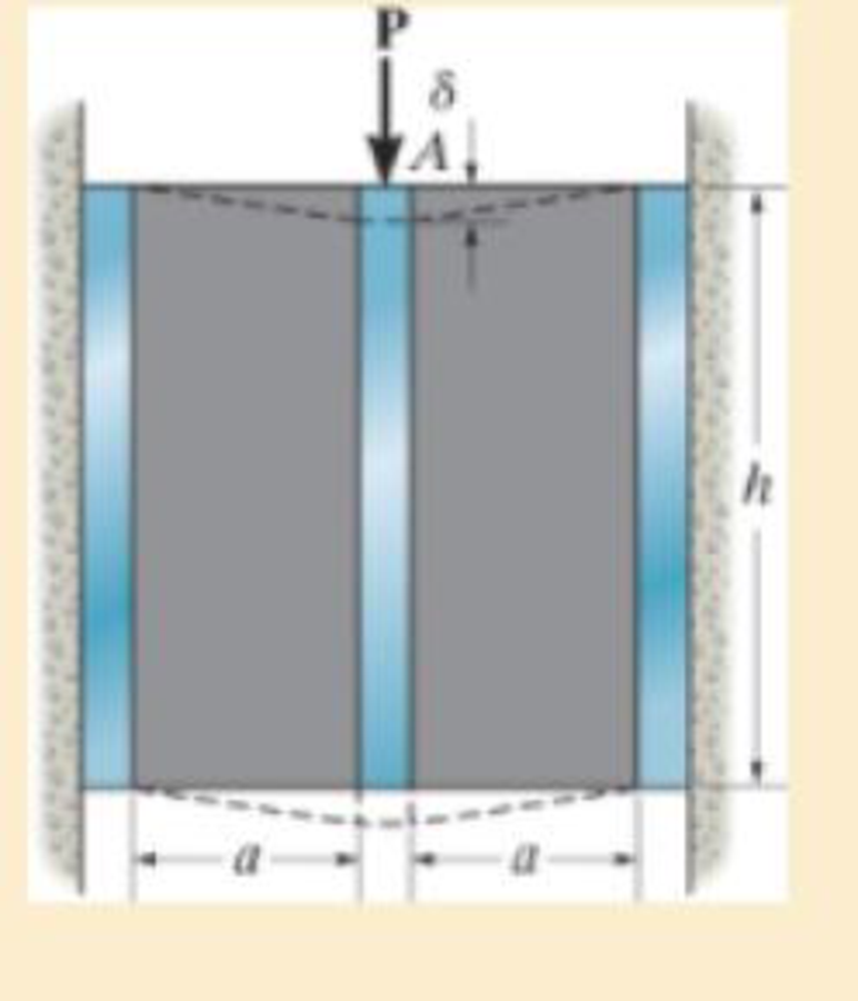
A shear spring is made from two blocks of rubber, each having a height h, width b, and thickness a. The blocks are bonded to three plates as shown. If the plates are rigid and the shear modulus of the rubber is G, determine the displacement of plate A when the vertical load P is applied. Assume that the displacement is small so that δ = a tan γ ≈ aγ.
Expert Solution & Answer
Want to see the full answer?
Check out a sample textbook solution
Students have asked these similar questions
Problem 2
The series of bars shown have their
diameters from left to right decreasing by 3 mm, and
lengths increasing correspondingly by 0.3 m. If the
leftmost member has a diameter and length of 28 mm,
1.8 m, respectively, determine the nodal displacements,
member forces and the value of P if the node where P
acts undergoes a rightward displacement of 4.5 mm.
E=180 GPa for all members. Use your calculator.
90 N/mm 45 N/mm
60 N/mm
30 KN
-50 KN
An acetal polymer block is fixed to the rigid plates at its top and bottom surfaces. If the top plate displaces 2 mm horizontally when it is subjected to a horizontal force P = 2 kN, determine the shear modulus of the polymer. The width of the block is 100 mm. Assume that the polymer is linearly elastic and use small-angle analysis.
Strains measured in a, b and c directions are yardımıa=-150x10-6, ɛb=200x10-6, and ɛc=300x10-6 with the help of the rosette placed at point A of the elastic material under the effect of plane tension. Calculate the principal stresses since the modulus of elasticity in the material is E= 200 GPa and the Poisson ratio ν= 0.3
Chapter 3 Solutions
Mechanics of Materials (10th Edition)
Ch. 3.4 - Define a homogeneous material.Ch. 3.4 - Indicate the points on the stress-strain diagram...Ch. 3.4 - Define the modulus of elasticity E.Ch. 3.4 - At room temperature, mild steel is a ductile...Ch. 3.4 - Engineering stress and strain are calculated using...Ch. 3.4 - As the temperature increases the modulus of...Ch. 3.4 - A 100-mm-long rod has a diameter of 15 mm. If an...Ch. 3.4 - A bar has a length of 8 in. and cross-sectional...Ch. 3.4 - A 10-mm-diameter rod has a modulus of elasticity...Ch. 3.4 - The material for the 50-mm-long specimen has the...
Ch. 3.4 - The material for the 50-mm-long specimen has the...Ch. 3.4 - If the elongation of wire BC is 0.2 mm after the...Ch. 3.4 - A tension test was performed on a steel specimen...Ch. 3.4 - Data taken from a stress-strain test for a ceramic...Ch. 3.4 - Data taken from a stress-strain test for a ceramic...Ch. 3.4 - The stress-strain diagram for a steel alloy having...Ch. 3.4 - The stress-strain diagram for a steel alloy having...Ch. 3.4 - The stress-strain diagram for a steel alloy having...Ch. 3.4 - The rigid beam is supported by a pin at C and an...Ch. 3.4 - The rigid beam is supported by a pin at C and an...Ch. 3.4 - Acetal plastic has a stress-strain diagram as...Ch. 3.4 - The stress-strain diagram for an aluminum alloy...Ch. 3.4 - The stress-strain diagram for an aluminum alloy...Ch. 3.4 - The stress-strain diagram for an aluminum alloy...Ch. 3.4 - A bar having a length of 5 in. and cross-sectional...Ch. 3.4 - The rigid pipe is supported by a pin at A and an...Ch. 3.4 - The rigid pipe is supported by a pin at A and an...Ch. 3.4 - Direct tension indicators are sometimes used...Ch. 3.4 - The rigid beam is supported by a pin at C and an...Ch. 3.4 - The rigid beam is supported by a pin at C and an...Ch. 3.4 - The stress-strain diagram for a bone is shown, and...Ch. 3.4 - The stress-strain diagram for a bone is shown and...Ch. 3.4 - The two bars are made of a material that has the...Ch. 3.4 - The two bars are made of a material that has the...Ch. 3.4 - The pole is supported by a pin at C and an A-36...Ch. 3.4 - The bar DA is rigid and is originally held in the...Ch. 3.7 - A 100-mm-long rod has a diameter of 15 mm. If an...Ch. 3.7 - A solid circular rod that is 600 mm long and 20 mm...Ch. 3.7 - A 20-mm-wide block is firmly bonded to rigid...Ch. 3.7 - A 20-mm-wide block is bonded to rigid plates at...Ch. 3.7 - The acrylic plastic rod is 200 mm long and 15 mm...Ch. 3.7 - The plug has a diameter of 30 mm and fits within a...Ch. 3.7 - The elastic portion of the stress-strain diagram...Ch. 3.7 - The elastic portion of the stress-strain diagram...Ch. 3.7 - The brake pads for a bicycle tire are made of...Ch. 3.7 - The lap joint is connected together using a 1.25...Ch. 3.7 - The lap joint is connected together using a 1.25...Ch. 3.7 - The rubber block is subjected to an elongation of...Ch. 3.7 - The shear stress-strain diagram for an alloy is...Ch. 3.7 - A shear spring is made from two blocks of rubber,...Ch. 3 - The elastic portion of the tension stress-strain...Ch. 3 - The elastic portion of the tension stress-strain...Ch. 3 - The rigid beam rests in the horizontal position on...Ch. 3 - The wires each have a diameter of 12 in., length...Ch. 3 - The wires each have a diameter of 12 in., length...Ch. 3 - diameter steel bolts. If the clamping force in...Ch. 3 - The stress-strain diagram for polyethylene, which...Ch. 3 - The pipe with two rigid caps attached to its ends...Ch. 3 - The 8-mm-diameter bolt is made of an aluminum...Ch. 3 - An acetal polymer block is fixed to the rigid...
Knowledge Booster


Learn more about
Need a deep-dive on the concept behind this application? Look no further. Learn more about this topic, mechanical-engineering and related others by exploring similar questions and additional content below.Similar questions
- The stepped rod is made up of two different materials A and B of lengths 80 cm and 1.2 m respectively. The diameters of materials B and A are 2.5 and 3.5 cm respectively. The modulus of elasticity of materials A and B are 250 and 150 GPa respectively. The elongation of the rod is the same for both the materials. A total tensile load of 40 kN is applied to both the materials A and B together. Calculate the load in each material.arrow_forwardThe spring has a stiffness of k = 800 N/m and an unstretched length of 200 mm. Determine the force in cables BC and BD when the spring is held in the position shown. 400 mm A k= 800 N/m gram (FBD) a tana =1 45* 4 a = 45° 300 mm 500 mm -400 mm- quilibriumarrow_forward4. A string has a diameter of 1 cm and the original length of 2 m. The string is pulled by a force of 200 N. Determine the change in length of the string! Young's modulus of the string = 5 x 10⁹ N/m²arrow_forward
- A straight bar 450 mm long is 10 mm in diameter for the first 200 mm length and 20 mm in diameter for the remaining length. If the bar is subjected to an axial push of 10 kN, determine decrease in length of the bar. Take modulus of elasticity of bar material E = 2 × 10⁵ N/mm²arrow_forwardPROBLEM 1/6 Determine the allowable weight that the assembly can handle if the cable AB has a working stress of 200 Mpa and cable AC has a working stress of 150 Mpa. The cable cross sectional areas are 300 mm? for cable AB and 330 mm? for cable AC. В C 50° 28° Warrow_forwardThe pipe is stuck in the ground so that when it is pulled upward the frictional force along its length varies linearly from zero at B to fmax (force/length) at C. The pipe has a length L, cross-sectional area A, and the material from which it is made has a modulus of elasticity E. Determine the initial force P required to pull the pipe out. Express your answer as an expression in terms of the variables f, L, A and E and any necessary constants.arrow_forward
- CDEFGH is plate with a circular hole in it and has a unit weight p = 2 kN/m². If the initial length of the spring is 1m, find the stretched length of the spring attached at C to the given system. The stiffness of the spring id k=50 kN/m. bwwwww.. 2 m H 0 D X 2 m 2 m G 2 m F E 3m 1marrow_forwardA force P of 70 N is applied by a rider to the front hand brake of a bicycle(Pis the resultant of an evenly distributed pressure). As the hand brakepivots at A. a tension T develops in the 460-mm Ions; brake cable (Ae=1.075 mm²), which elongates by δ 6=0.214 mm. Find the normal stress 8and strain e in the brake cable.Brake cable, L = 460 mmHand brake pivot Aarrow_forwardThe spring ABC has a stiffness of 500N/m and an unstretched length of 6m. Calculate the horizontal force, F applied to the cord which is attached at B so that the displacement of the pulley from the wall is d= 1.5m. A k = 500 N/m 6 m F k = 500 N/m Fig. Q3 Force equation: Force equation 3D Moment 3D Cosine rule R - 4 +B-2AB cos e F- Fi+Fj+Fk Ff = F +F +F moment about a point M-rxF Sine rule F| di+dj+dk F F3 Fc sin 4 sin B sinC moment about an axis M=rF Force resultant R-R R +R R. 8= tan Rarrow_forward
- A rubber pad is sandwiched between two steel plates subjected to shear force V = 400kN. The dimensions of the plate area, a= 250mm and b = 300mm. The thickness of the rubber is c = 125mm. After the force is applied, the top plate is found to have displaced laterally by δ = 1.5mm along the 300mm length. Determine the shear stress. Determine the shear strain. Determine the shear modulus.arrow_forwardThe 200 mm long and 20 mm diameter solid circular rod is subjected to an axial force of P. P = 400 and δ = 1.6. ElasticityCalculate the modulus E and the shear modulus G. Take 0.3 Poisson's ratio.arrow_forward3. As shown, a 50-kg rigid block is suspended by the three springs whose lower ends were originally at the same level. Each steel spring has 24 turns of 5-mm-radius on a mean diameter of 100 mm, and G = 83 GPa. The bronze spring has 48 turns of 10-mm-radius wire on a mean diameter of 150 mm, and G = 42 GPa. Compute the maximum shearing stress in each spring. Phosphor Bronaw Stel 2m 50 kg 1marrow_forward
arrow_back_ios
SEE MORE QUESTIONS
arrow_forward_ios
Recommended textbooks for you
 Elements Of ElectromagneticsMechanical EngineeringISBN:9780190698614Author:Sadiku, Matthew N. O.Publisher:Oxford University Press
 Mechanics of Materials (10th Edition)Mechanical EngineeringISBN:9780134319650Author:Russell C. HibbelerPublisher:PEARSON
 Thermodynamics: An Engineering ApproachMechanical EngineeringISBN:9781259822674Author:Yunus A. Cengel Dr., Michael A. BolesPublisher:McGraw-Hill Education
 Control Systems EngineeringMechanical EngineeringISBN:9781118170519Author:Norman S. NisePublisher:WILEY
 Mechanics of Materials (MindTap Course List)Mechanical EngineeringISBN:9781337093347Author:Barry J. Goodno, James M. GerePublisher:Cengage Learning
 Engineering Mechanics: StaticsMechanical EngineeringISBN:9781118807330Author:James L. Meriam, L. G. Kraige, J. N. BoltonPublisher:WILEY
Elements Of Electromagnetics
Mechanical Engineering
ISBN:9780190698614
Author:Sadiku, Matthew N. O.
Publisher:Oxford University Press
Mechanics of Materials (10th Edition)
Mechanical Engineering
ISBN:9780134319650
Author:Russell C. Hibbeler
Publisher:PEARSON
Thermodynamics: An Engineering Approach
Mechanical Engineering
ISBN:9781259822674
Author:Yunus A. Cengel Dr., Michael A. Boles
Publisher:McGraw-Hill Education
Control Systems Engineering
Mechanical Engineering
ISBN:9781118170519
Author:Norman S. Nise
Publisher:WILEY
Mechanics of Materials (MindTap Course List)
Mechanical Engineering
ISBN:9781337093347
Author:Barry J. Goodno, James M. Gere
Publisher:Cengage Learning
Engineering Mechanics: Statics
Mechanical Engineering
ISBN:9781118807330
Author:James L. Meriam, L. G. Kraige, J. N. Bolton
Publisher:WILEY
EVERYTHING on Axial Loading Normal Stress in 10 MINUTES - Mechanics of Materials; Author: Less Boring Lectures;https://www.youtube.com/watch?v=jQ-fNqZWrNg;License: Standard YouTube License, CC-BY