
Tutorials in Introductory Physics
1st Edition
ISBN: 9780130970695
Author: Peter S. Shaffer, Lillian C. McDermott
Publisher: Addison Wesley
expand_more
expand_more
format_list_bulleted
Videos
Textbook Question
Chapter 24.5, Problem 2cTH
Repeat parts a andb for the case in which lens 2 is replaced with a different lens (lens 3), as shown below.
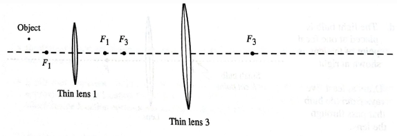
Is the image produced by the pair of lenses real or virtual? Explain your reasoning.
Expert Solution & Answer
Want to see the full answer?
Check out a sample textbook solution
Students have asked these similar questions
A concave lens refracts parallel rays in such a way that they are bent away from the axis of the lens. For this reason, a concave lens is referred to as a diverging lens.
Part A: Consider the following diagrams, where F represents the focal point of a concave lens. In these diagrams, the image formed by the lens is obtained using the ray tracing technique. Which diagrams are accurate?(Figure 1)
*Type A if you think that only diagram A is correct, type AB if you think that only diagrams A and B are correct, and so on.
Part B: If the focal length of the concave lens is -7.50 cm , at what distance d_o from the lens should an object be placed so that its image is formed 3.70 cm from the lens?
Case 1: Object distance d0= infinity. The figure below shows light rays coming from an object located at infinity, in front of a convex lens. Extend the 9 incident rays to the lens, and draw the transmitted rays in the correct direction. Use the figure, DO NOT substitute it with any other figure. Use the line to trace the 9 rays. Don't forget to place the arrow on each transmitted beam. Label each ray with its corresponding name: parallel ray, central ray, and focal ray.
Image characteristics for Case 1: Object distance d0= infinity. Select those that apply:
a) Reduced
b) Real
c) Erect
d) Inverted
e) Equal size
f) Increased
g) Virtual
h) No image is formed
Part A
The diagram below shows the situation described in the problem. The focal length of the lens is labeled f; the scale on the
optical axis is in centimeters.Draw the three special rays Ray1, Ray2, and Ray3 as described in the Tactics Box above, and
label each ray accordingly. Draw the rays from the tip of the object to the lens. Do not draw the refracted rays.
Draw the vectors starting from the tip of the object. The location and orientation of the vectors will be graded. The
length of the vectors will not be graded.
+,
Vectors:
Ray3 Ray through center of lens
Ray2 Ray toward far focal point
Rayl Ray parallel to axis
Unlabeled vector
Object
1
Chapter 24 Solutions
Tutorials in Introductory Physics
Ch. 24.1 - On the diagram, sketch what you would see on the...Ch. 24.1 - The small bulb is replaced by three longfilament...Ch. 24.1 - The three longfilament bulbs are replaced by a...Ch. 24.1 - Predict the size and shape of the shadow that will...Ch. 24.1 - Is it possible to place the bulb in another...Ch. 24.1 - Prob. 2cTHCh. 24.1 - Prob. 2dTHCh. 24.1 - Prob. 3aTHCh. 24.1 - A student is looking at the building shown at...Ch. 24.1 - Prob. 4aTH
Ch. 24.1 - Suppose that this student were walking through the...Ch. 24.2 - The top view diagrams at right were drawn by a...Ch. 24.2 - Draw a ray diagram to determine the location of...Ch. 24.2 - Describe how you could use a ray diagram to...Ch. 24.2 - A pencil is placed in front of a plane mirror as...Ch. 24.2 - Prob. 3bTHCh. 24.3 - Prob. 1aTHCh. 24.3 - A pin is placed in front of a semicylindrical...Ch. 24.3 - Prob. 1cTHCh. 24.3 - Prob. 2aTHCh. 24.3 - A very small, very bright bulb is placed for from...Ch. 24.4 - The following are top view diagrams of solid...Ch. 24.4 - The following are top view diagrams of solid...Ch. 24.4 - The following are top view diagrams of solid...Ch. 24.4 - The following are top view diagrams of solid...Ch. 24.4 - Prob. 2THCh. 24.4 - Prob. 3aTHCh. 24.4 - Prob. 3bTHCh. 24.4 - Is the image(s) of the nail real or virtual?...Ch. 24.5 - Suppose that the bulb is placed as shown. Using...Ch. 24.5 - Prob. 1bTHCh. 24.5 - Prob. 1cTHCh. 24.5 - Prob. 1dTHCh. 24.5 - Prob. 2aTHCh. 24.5 - Treat the image produced by lens 1 as an object...Ch. 24.5 - Repeat parts a andb for the case in which lens 2...Ch. 24.6 - Reproduced below is a side view diagram of the...Ch. 24.6 - In section III of the tutorial Magnification, you...Ch. 24.6 - Two thin convex lenses and an object are arranged...Ch. 24.6 - Prob. 3bTHCh. 24.6 - Two thin convex lenses and an object are arranged...Ch. 24.6 - Prob. 3dTHCh. 24.6 - Two thin convex lenses and an object are arranged...
Additional Science Textbook Solutions
Find more solutions based on key concepts
A plank, fixed to a sled at rest in frame S, is of length L0 and makes an angle of 0 with the xaxis. Later, the...
Modern Physics
3. What is free-fall, and why does it make you weightless? Briefly describe why astronauts are weightless in th...
The Cosmic Perspective (8th Edition)
TEST YOUR UNDERSTANDING OF SECTION 37.2 Stanley, who works for the rail system shown in Fig. 37.5, has carefull...
University Physics with Modern Physics (14th Edition)
Under what circumstances is the path of a charged particle a parabola? A circle?
Essential University Physics: Volume 2 (3rd Edition)
Another property of light is the energy. Which of the following has the greatest energy (circle one)?
Lecture- Tutorials for Introductory Astronomy
Knowledge Booster


Learn more about
Need a deep-dive on the concept behind this application? Look no further. Learn more about this topic, physics and related others by exploring similar questions and additional content below.Similar questions
- An object, pointing upwards, is placed outside the focal point F2 of a thin diverging lens. A student is using the diagram shown above and the graphical method to predict the image of the arrow. To draw a principal ray, which direction should the student follow? O Draw a ray from point Q through F, to the lens, then bend it so it is horizontal. O Draw a horizontal ray from point Q to the lens, then bend it so it appears to diverge from F2. O Draw a ray from point P to any position on the lens, then bend it so it is horizontal. Draw a ray from point Q to the center of the lens, then bend it so it is horizontal.arrow_forwardIn the figure at right the light is crossing a vertical interface with the normal Medium n1 marked as a dashed line. The light is coming from the left and crossing to the right.. Medium n2 normal Which is larger? The index of refraction is larger The speed of light is faster in Choose the equation or equations that you will need to use to calculate n2 given the angles of incidence and refraction and then to find the speed of light in medium n2. Select one or more: a. Force on an object mass m moving in a circle of radius R: F = mv2/R b. B-field of a long straight wire: B = Hol/2nR c. Snell's law: n;sin0, = n2sin02 d. Doppler shift: f' = f(1 ± u/c) e. C = = fA f. Magnetic Force on a moving charge: F = qvBsin0 g. Force on a current carrying wire: F = BILsine h. Mirror or Thin Lens Equation: 1/d, + 1/d; =1/f, h/h¡ = -d/d;arrow_forwardYou are imaging a pencil through a thin, converging lens as shown in the image below. If p (the distance from the object to the center of the thin lens) is 8.15m and the focal length of the thin lens is 0.42m, how far away (in meters) from the center of the thin lens is the real image located (the real image will be on the right-side of the lens in this particular example illustrated below)? Ray 1 Ray 1 focal point Ray 2 Sis Secondary Ray 3 Ray 3 Object Converging lens focal point Principal Real image Note: Do not explicitly include units in your answer (it is understood the unit is meter). Enter only a number. If you do enter a unit, your answer will be counted wrong.arrow_forward
- Suppose you know the six cardinal points of an optical system (two focal points F1 and F2, two principal points H1 and H₂ and two nodal points N₁ and N₂), complete the three special rays to locate the image position formed by this system. Label the focal lengths, object distance and image distance. [Hint: A ray parallel to optical axis, turns to the focal point F2 after passing through the principle plane H₂. A ray through Fi will turn to parallel after H₁. A ray moving towards to N₁ will emerge at N₂ with the same angle. In a thick lens, N overlaps with H point if the refractive index is the same on both sides of the lens.] F₁ H1 N₁ H₂ N₂ F₂arrow_forwardYou are imaging a pencil through a thin, converging lens as shown in the image below. If p (the distance from the object to the center of the thin lens) is 6.86m and the focal length of the thin lens is 1.4m, how far away (in meters) from the center of the thin lens is the real image located (the real image will be on the right-side of the lens in this particular example illustrated below)? Ray 1 Page Object focal point Converging lens Ray 2 Secondary Ray 3 Ray 1 Ray 3 Principal focal point Real imagearrow_forwardThe diagram below shows the situation described in the problem. The focal length of the lens is labeled f; the scale on the optical axis is in centimeters. Draw the three special rays, Ray1, Ray2, and Ray3 as described in the Tactics Box above, and label each ray accordingly. Draw the rays from the tip of the object to the center vertical axis of the lens. Do not draw the refracted rays. Draw the vectors for the incident rays starting at the tip of the object to the center vertical axis of the lens. The location and orientation of the vectors will be graded. Vectors: Ray3 Ray though center of lens Ray2 Ray through near focal point Rayl Ray parallel to axis Unlabeled vector Objectarrow_forward
- I Review A coin is lying at the bottom of a pool of water that is 7.3 feet deep. Part A Viewed from directly above the coin, how far below the surface of the water does the coin appear to be? (The coin is assumed to be small in diameter; therefore, we can use the small-angle approximations sine = tan0 = 0.) Express your answer using two significant figures. ν ΑΣφ ? dapp ft Submit Request Answer < Return to Assignment Provide Feedback IIarrow_forwardAn object and screen are located as shown below, and a converging lens is placed between them. The lens produces a sharp image of the object on the screen. On the diagram, draw two principal rays from the top of the object (i.e. tip of the pencil) to the screen that will allow you to locate both focal points of the lens, and label these points on the diagram. Explain the reasoning used to determine the answer. On the diagram of the previous question, it is known that the distance between the lens and the object is twice the distance between the lens and the screen. It is also found that by moving the object closer to the lens by 12 cm, the lens produces a lateral magnification of –1 (of course the screen is also moved in the process). Compute the focal length of the lens in cm. Please show workarrow_forwardA plane wave hits a piece of glass whose front surface is spherical and whose back surface is plane. The radius of the lens is 10 cm and the thickness of the glass is 1 cm at the center, as shown in the diagram at right. At time t1, the center of the plane wavefront has just reached the lens. A short time later, at time t2, the center of the wavefront will have passed completely through the glass, as shown. a) Find the time that elapses between t1 and t2, the time it takes the center of the wavefront to pass thorugh the middle 1 cm of the glass. b) Find the amount by which the edges of the wavefront at t2 will be ahead of the cetner of the wavefront, due to the fact that these edges passed through empty space, with no glass in their paths.arrow_forward
- A beam of light in air is incident at an angle of 30° to the surface of a rectangular block of clear water (n =1.33). What is angle between incident and refracted beam? Use algebra and explain your steps. Please show how to solve step by step.arrow_forwardE F D В Here, we're looking down on a room with 6 people. The bottom wall (including point X) and the left wall are mirrored. Person F fires a laser beam at point X. Who gets hit by the laser? In your answer below, include your reasoning and reflected angles for full credit. If more than one person is in the possible path, indicate that as well (the first person might duck out of the way!).arrow_forwardAn image seen through a convex mirror cut from a sphere of radius 20cm is exactly half size of the object. Where must the object and image be located? Support your work with a ray diagram. Hint: Remember that virtual distances are negative when using the mirror equation. Follow grading rubric. Explain answer.arrow_forward
arrow_back_ios
SEE MORE QUESTIONS
arrow_forward_ios
Recommended textbooks for you
 College PhysicsPhysicsISBN:9781305952300Author:Raymond A. Serway, Chris VuillePublisher:Cengage Learning
 University Physics (14th Edition)PhysicsISBN:9780133969290Author:Hugh D. Young, Roger A. FreedmanPublisher:PEARSON
 Introduction To Quantum MechanicsPhysicsISBN:9781107189638Author:Griffiths, David J., Schroeter, Darrell F.Publisher:Cambridge University Press
 Physics for Scientists and EngineersPhysicsISBN:9781337553278Author:Raymond A. Serway, John W. JewettPublisher:Cengage Learning
 Lecture- Tutorials for Introductory AstronomyPhysicsISBN:9780321820464Author:Edward E. Prather, Tim P. Slater, Jeff P. Adams, Gina BrissendenPublisher:Addison-Wesley
 College Physics: A Strategic Approach (4th Editio...PhysicsISBN:9780134609034Author:Randall D. Knight (Professor Emeritus), Brian Jones, Stuart FieldPublisher:PEARSON
College Physics
Physics
ISBN:9781305952300
Author:Raymond A. Serway, Chris Vuille
Publisher:Cengage Learning
University Physics (14th Edition)
Physics
ISBN:9780133969290
Author:Hugh D. Young, Roger A. Freedman
Publisher:PEARSON
Introduction To Quantum Mechanics
Physics
ISBN:9781107189638
Author:Griffiths, David J., Schroeter, Darrell F.
Publisher:Cambridge University Press
Physics for Scientists and Engineers
Physics
ISBN:9781337553278
Author:Raymond A. Serway, John W. Jewett
Publisher:Cengage Learning
Lecture- Tutorials for Introductory Astronomy
Physics
ISBN:9780321820464
Author:Edward E. Prather, Tim P. Slater, Jeff P. Adams, Gina Brissenden
Publisher:Addison-Wesley
College Physics: A Strategic Approach (4th Editio...
Physics
ISBN:9780134609034
Author:Randall D. Knight (Professor Emeritus), Brian Jones, Stuart Field
Publisher:PEARSON
Domestic Electric Circuits; Author: PrepOnGo Class 10 & 12;https://www.youtube.com/watch?v=2ZvWaloQ3nk;License: Standard YouTube License, CC-BY