
Applied Statics and Strength of Materials (6th Edition)
6th Edition
ISBN: 9780133840544
Author: George F. Limbrunner, Craig D'Allaird, Leonard Spiegel
Publisher: PEARSON
expand_more
expand_more
format_list_bulleted
Concept explainers
Videos
Textbook Question
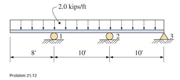
Chapter 21, Problem 21.12P
For the continuous beams shown, find moments at the supports and the reactions. Draw complete shear and moment diagrams.
Expert Solution & Answer
Want to see the full answer?
Check out a sample textbook solution
Students have asked these similar questions
Find the reactions of the structure and draw the shear and moment diagrams for the beam (Use the Force Method).
Find reactions at A and Ma.
Give the (signed) values of the largest shear and bending moment occurring anywhere within the beam.
Draw the corresponding shear and bending moment diagram.
For the beam shown, find the reactions at the supports and plot the shear-force and bending-moment diagrams. Label the diagrams properly and provide values at all key points.
Chapter 21 Solutions
Applied Statics and Strength of Materials (6th Edition)
Ch. 21 - Prob. 21.1PCh. 21 - Prob. 21.2PCh. 21 - Use the method of superposition to determine the...Ch. 21 - Draw complete shear and moment diagrams for the...Ch. 21 - Draw complete shear and moment diagrams for the...Ch. 21 - Draw complete shear and moment diagrams for the...Ch. 21 - Determine the reactions for the beam shown.Ch. 21 - Prob. 21.8PCh. 21 - 21.9 Select a southern pine timber beam () for the...Ch. 21 - For the continuous beams shown, find moments at...
Ch. 21 - For the continuous beams shown, find moments at...Ch. 21 - For the continuous beams shown, find moments at...Ch. 21 - Prob. 21.13SPCh. 21 - Prob. 21.14SPCh. 21 - Prob. 21.15SPCh. 21 - Prob. 21.16SPCh. 21 - Prob. 21.17SPCh. 21 - Prob. 21.18SPCh. 21 - Prob. 21.19SPCh. 21 - Prob. 21.20SPCh. 21 - For these problems, use any appropriate method of...Ch. 21 - For these problems, use any appropriate method of...Ch. 21 - Prob. 21.23SPCh. 21 - For these problems, use any appropriate method of...
Knowledge Booster


Learn more about
Need a deep-dive on the concept behind this application? Look no further. Learn more about this topic, mechanical-engineering and related others by exploring similar questions and additional content below.Similar questions
- For the 2-shear diagram shown below, provide the beam loadings and the moment diagram in line with the shear diagram. Utilize the space provided below each diagram to draw the beam loadings and moment diagram. Provide also equations only at the first two sections of the beam from left to right.arrow_forwardFor the beam shown, derive the expressions for V and M, and draw the shear force and bending moment diagrams. Calculate the shear force V and bending moment M at a cross section located 0.5 m from the fixed support. Neglect the weight of the beam. (Show complete calculation and step by step process. Show free body diagram)arrow_forwardFind the reactions and draw the shear and bending moment diagrams.arrow_forward
- For the structure shown, calculate the reactions and draw the shear and bending moment diagrams.arrow_forwardFor the beam shown below, provide equations at each section. Draw the shear and moment diagram of the beam on the space provided below.arrow_forward2. For the 20 meter beam shown, there is a roller at "A" (Ay = 52 kN; it is acting upward), and a pin joint at "B" (By=-- 17 kN; it is acting downward). (a) Draw complete shear force and bending moment diagrams. (b) If x=0 is at the left end of the beam, write equations for the shear force and bending moment, and indicate the appropriate sections. (You may use the table on the next page.) 50 KN 15 KN A 90 kN-m 2 m3 m -5 m B *4 -7 m 120 kN-m € 3 marrow_forward
- For the beam shown, find the reactions at the supports and plot the shear-force and bending-moment diagrams. Label the diagrams properly and provide values at all key points within the diagrams.arrow_forwardFigure 1 below shows a 5 m length of beam with a pinned support at A and roller support at E. The beam carries three concentrated loads of 10 kN, 5 kN and 15 kN at B, C and D, respectively. а. Show the Free Body Diagram (FBD) of the beam then determine the reaction force. b. Calculate the shear force, V. Draw Shear Force Diagram (SFD). Calculate the bending moment, M. Draw the Bending Moment Diagram (BMD). 10 kN 5 kN 15 kN A E B C D 1m 1m 1 m 2 m Figure 1 C.arrow_forwardUsing the method of sections determine the reactions at the supports, draw the bending moment and shear diagrams for the beam and shipments shown in the figure below.arrow_forward
- Draw the shear diagram for the beam and the moment diagram. Please explain it ASAP.arrow_forwardFor the beam shown in the figure, Calculate the support reaction forces and find the internal forces and moments at a point located 2 m from the right support and then draw the shear and moment diagram for this beam.arrow_forwardUse Singularity functions to draw the shear and bending moment diagram for this beam problem in terms of F and L.arrow_forward
arrow_back_ios
SEE MORE QUESTIONS
arrow_forward_ios
Recommended textbooks for you
 Elements Of ElectromagneticsMechanical EngineeringISBN:9780190698614Author:Sadiku, Matthew N. O.Publisher:Oxford University Press
 Mechanics of Materials (10th Edition)Mechanical EngineeringISBN:9780134319650Author:Russell C. HibbelerPublisher:PEARSON
 Thermodynamics: An Engineering ApproachMechanical EngineeringISBN:9781259822674Author:Yunus A. Cengel Dr., Michael A. BolesPublisher:McGraw-Hill Education
 Control Systems EngineeringMechanical EngineeringISBN:9781118170519Author:Norman S. NisePublisher:WILEY
 Mechanics of Materials (MindTap Course List)Mechanical EngineeringISBN:9781337093347Author:Barry J. Goodno, James M. GerePublisher:Cengage Learning
 Engineering Mechanics: StaticsMechanical EngineeringISBN:9781118807330Author:James L. Meriam, L. G. Kraige, J. N. BoltonPublisher:WILEY
Elements Of Electromagnetics
Mechanical Engineering
ISBN:9780190698614
Author:Sadiku, Matthew N. O.
Publisher:Oxford University Press
Mechanics of Materials (10th Edition)
Mechanical Engineering
ISBN:9780134319650
Author:Russell C. Hibbeler
Publisher:PEARSON
Thermodynamics: An Engineering Approach
Mechanical Engineering
ISBN:9781259822674
Author:Yunus A. Cengel Dr., Michael A. Boles
Publisher:McGraw-Hill Education
Control Systems Engineering
Mechanical Engineering
ISBN:9781118170519
Author:Norman S. Nise
Publisher:WILEY
Mechanics of Materials (MindTap Course List)
Mechanical Engineering
ISBN:9781337093347
Author:Barry J. Goodno, James M. Gere
Publisher:Cengage Learning
Engineering Mechanics: Statics
Mechanical Engineering
ISBN:9781118807330
Author:James L. Meriam, L. G. Kraige, J. N. Bolton
Publisher:WILEY
Understanding Shear Force and Bending Moment Diagrams; Author: The Efficient Engineer;https://www.youtube.com/watch?v=C-FEVzI8oe8;License: Standard YouTube License, CC-BY
Bending Stress; Author: moodlemech;https://www.youtube.com/watch?v=9QIqewkE6xM;License: Standard Youtube License