
Applied Statics and Strength of Materials (6th Edition)
6th Edition
ISBN: 9780133840544
Author: George F. Limbrunner, Craig D'Allaird, Leonard Spiegel
Publisher: PEARSON
expand_more
expand_more
format_list_bulleted
Concept explainers
Videos
Textbook Question
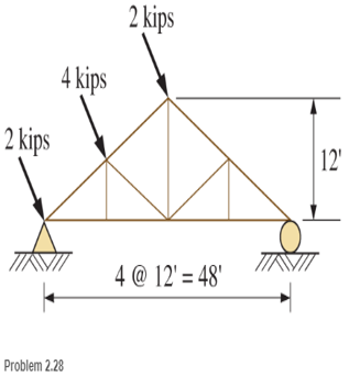
Chapter 2, Problem 2.28SP
The Howe roof truss shown is subjected to wind loads as shown. The wind loads are perpendicular to the inclined top chord. Resolve each into vertical and horizontal components.
Expert Solution & Answer
Want to see the full answer?
Check out a sample textbook solution
Students have asked these similar questions
A group of cell- phone antennas are to be installed on a single steel pole that will be embedded into a dense silty sand with Φ' = 35°. Near the ground surface this pole will be connected to a 24 in diameter drilled shaft. The resultant of the lateral wind load will be 600 lb and will act at a point 50 ft above the ground surface. Using a rigid analysis, compute the required depth of embedment and the maximum moment in the drilled shaft. Use a factor of safety of 3.0.
The truss above has concentrated loads as shown. The wind loads of 25 KN are perpendicular to the member AF.
The forces acting on all members by the method of sections
The truss above has concentrated loads as shown. The wind loads of 25 KN are perpendicular to the member AF.
The forces acting on all the members by the method of joints.
Chapter 2 Solutions
Applied Statics and Strength of Materials (6th Edition)
Ch. 2 - Find the resultant force for each system of forces...Ch. 2 - Rework Problem 2.1 solving for the resultants...Ch. 2 - Compute the vertical and horizontal components for...Ch. 2 - Compute the vertical and horizontal components for...Ch. 2 - Compute the vertical and horizontal components for...Ch. 2 - The rectangular components of a force are...Ch. 2 - Find the resultant force on the screw eye. One...Ch. 2 - Write a program that will calculate the...Ch. 2 - Write a program that will calculate me magnitude...Ch. 2 - Calculate and display the vertical and horizontal...
Ch. 2 - A plastic barrel containing water is used as an...Ch. 2 - A telephone pole is braced by a guy wire that...Ch. 2 - Compute the vertical and horizontal components for...Ch. 2 - Compute the vertical and horizontal components of...Ch. 2 - Compute the rectangular components parallel and...Ch. 2 - Determine the vertical and horizontal components...Ch. 2 - Find the vertical and horizontal components of...Ch. 2 - An inclined cable is used to pull on a log as...Ch. 2 - In Problem 2.18 , if the log will slide when a...Ch. 2 - A rope is bed to the top of a 10-m flagpole The...Ch. 2 - A rope tow is used to pull skiers up a...Ch. 2 - Determine the slope triangle dimension s so that...Ch. 2 - The crane wheel applies a 9500-lb forte to the...Ch. 2 - The horizontal and vertical components,...Ch. 2 - Calculate the X and Y components of each force...Ch. 2 - Find the resultant of the two force acting on the...Ch. 2 - A drawbar support assembly is shown in the figure....Ch. 2 - The Howe roof truss shown is subjected to wind...Ch. 2 - The release cam mechanism is subjected to the...
Knowledge Booster


Learn more about
Need a deep-dive on the concept behind this application? Look no further. Learn more about this topic, mechanical-engineering and related others by exploring similar questions and additional content below.Similar questions
- Construct the shear force and bending moment diagrams for the beam shown by the area method. Neglect the weight of the beam.arrow_forwardProblem 4. Solve for the resultant of the six loads on the truss shown below. The loads are given in kips (K) (1 kip = 1000 lb). Three loads are vertical. The wind loads are perpendicular to the side. The truss is symmetrical. Solve for the reactions at the supports as well. 3K 1K 2 K 2 K 2 K 10' 10 900 90° 300arrow_forwardCalculate the shear force V at the midpoint of the beamarrow_forward
- Calculate the applied moment at each knee when the person’s upper body is angled 60° from the ground. Assume mbody = 30 kg, mthigh = 9 kg, mshank = 5 kg and the centre of mass for each segment is located at the midpoint of the segment. state any assumptionsarrow_forwardPROBLEM 2: The roof truss shown is supported on rollers at A and is hinged at B. The wind loads H1, H2, and H3, actperpendicular to the top chord. Analyze the truss based on the stated conditions. Indicate “C” for compression and “T”for tension.Given:S = 3.0 mH = 1.5 m Required: 1. Force in member DC (kN). (Answer: 36.224 (T))Given: H1 = 16 kN; H2 = 27 kN; H3 = 11 kN; P = 105 kN 2. Force in member FC (kN). (Answer: 234.686 (C))Given: H1 = 16 kN; H2 = 27 kN; H3 = 11 kN; P = 105 kNarrow_forwardProblem 1: For the shown beam: 15 kN/m a. Calculate the Equivalent Concentrated force FR for 3 KN 5 kN/m 1 KN the shown distributed load. 50 b. Resolve all forces in their X and Y components. 12 m C. Find the total Fx and Fyacting on this beam.arrow_forward
- The truss shown is one of several supporting an advertising panel. Determine the force in each member of the truss for a wind load equivalent to the two forces shown. State whether each member is in tension or compression.arrow_forwardExample 314: To facilitate shifting the position of a lifting hook when it is not under load, the sliding hanger shown is used. The projections at A and Bengage the flanges of a box beam when a Joad is supported, and the hook projects through a horizontal slot in the beam. Compute the forces at A and Bwhen the hook supports a 300-kg mass. Ans. A = 4.9 kN, B= 1,9 kN 400 600 mm mm A 300 ५४arrow_forwardCalculate the axial force in each member of the truss shown. Be sure to indicate the magnitude, units, and either tension (T) or compression (C) for each member force. 4 ft 4 ft A E 8 kip 10 kip 3 ftarrow_forward
- The truss above has concentrated loads as shown. The wind loads of 50 KN are perpendicular to the member AF. Solve for the forces acting on the members HI, GI, JI, HJ, FI by the method of joints.arrow_forwardIn figure below compute the net force exerted on the hemispherical shape located at the bottom of the container.arrow_forwardThe structure shown below is hinged to fixed supports at A and C. The bars are each 4 in. by 4 in. in section. Compute the maximum moment in member BC.arrow_forward
arrow_back_ios
SEE MORE QUESTIONS
arrow_forward_ios
Recommended textbooks for you
 International Edition---engineering Mechanics: St...Mechanical EngineeringISBN:9781305501607Author:Andrew Pytel And Jaan KiusalaasPublisher:CENGAGE L
International Edition---engineering Mechanics: St...
Mechanical Engineering
ISBN:9781305501607
Author:Andrew Pytel And Jaan Kiusalaas
Publisher:CENGAGE L
Introduction To Engg Mechanics - Newton's Laws of motion - Kinetics - Kinematics; Author: EzEd Channel;https://www.youtube.com/watch?v=ksmsp9OzAsI;License: Standard YouTube License, CC-BY