
Applied Statics and Strength of Materials (6th Edition)
6th Edition
ISBN: 9780133840544
Author: George F. Limbrunner, Craig D'Allaird, Leonard Spiegel
Publisher: PEARSON
expand_more
expand_more
format_list_bulleted
Concept explainers
Videos
Textbook Question
Chapter 15, Problem 15.40P
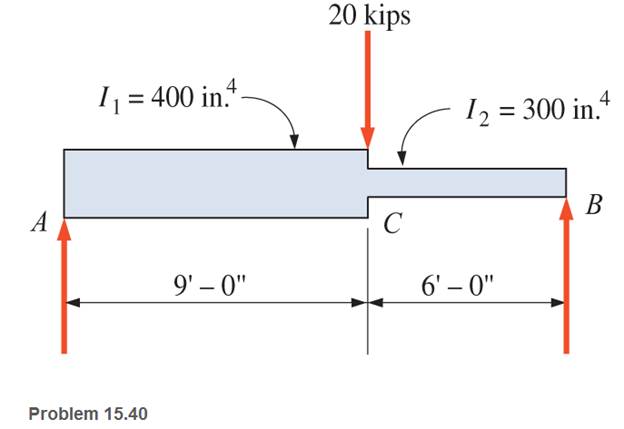
For Problems 15.31 through 15.43, use the moment-area method.
15.40 Calculate the maximum deflection for the simply supported steel beam shown. Neglect the weight of the beam.
Expert Solution & Answer
Want to see the full answer?
Check out a sample textbook solution
Students have asked these similar questions
Given the Cantilever beam loaded as shown, determine the deflection of the beam at the right end by using Three Moment Equation (TME). Note: The unit obtained from TME for EIy is kips-ft^3.
Solve for the moments and reactions at the fixed supports. You MUST use the slope deflection method.
(use EI constant for whole span). A 10-meter-span, propped beam (fixed at the left support and roller at right support), with a uniformly distributed load from left support to six meters to the right, with a magnitude of six kilonewton per lineal meter, a downward concentrated load at the midspan. Solve the reactions at the fixed support and roller support, slope and deflection at the roller support, using Area Moment Method. Use the concentrated load as 24 kN.
Chapter 15 Solutions
Applied Statics and Strength of Materials (6th Edition)
Ch. 15 - A 14 in.-diameter aluminum rod is bent into a...Ch. 15 - 15.2 Calculate the maximum bending stress produced...Ch. 15 - A 500 -mm-long steel bar having a cross section of...Ch. 15 - 15.4 An aluminum wire has a diameter of in....Ch. 15 - 15.5 A -in.-wide by in.-thick board is bent to a...Ch. 15 - 15.6 A Douglas fir beam is in. wide and in. deep....Ch. 15 - Prob. 15.7PCh. 15 - For Problems 15.7 through 15.14, use the formula...Ch. 15 - For Problems 15.7 through 15.14, use the formula...Ch. 15 - For Problems 15.7 through 15.14, use the formula...
Ch. 15 - For Problems 15.7 through 15.14, use the formula...Ch. 15 - For Problems 15.7 through 15.I4, use the formula...Ch. 15 - For Problems 15.7 through 15.14, use the formula...Ch. 15 - For Problems 15.7 through 15.14, use the formula...Ch. 15 - For Problems 15.15 through 15.26, use the...Ch. 15 - For Problems 15.15 through 15.26, use the...Ch. 15 - For Problems 15.15 through 15.26, use the...Ch. 15 - For Problems 15.15 through 15.26, use the...Ch. 15 - For Problems 15.15 through 15.26, use the...Ch. 15 - For Problems 15.15 through 15.26, use the...Ch. 15 - For Problems 15.15 through 15.26, use the...Ch. 15 - For Problems 15.15 through 15.26, use the...Ch. 15 - For Problems 15.15 through 15.26, use the...Ch. 15 - For Problems 15.15 through 15.26, use the...Ch. 15 - For Problems 15.15 through 15.26, use the...Ch. 15 - For Problems 15.15 through 15.26, use the...Ch. 15 - 15.27 Draw the moment diagram by parts for the...Ch. 15 - 15.28 Draw the moment diagram by parts for the...Ch. 15 - 15.29 Draw the moment diagram by parts for the...Ch. 15 - 15.30 For the beam shown, draw the conventional...Ch. 15 - For Problems 15.31 through 15.43, use the...Ch. 15 - For Problems 15.31 through 15.43, use the...Ch. 15 - For Problems 15.31 through 15.43, use the...Ch. 15 - For Problems 15.31 through 15.43, use the...Ch. 15 - For Problems 15.31 through 15.43, use the...Ch. 15 - For Problems 15.31 through 15.43, use the...Ch. 15 - For Problems 15.31 through 15.43, use the...Ch. 15 - For Problems 15.31 through 15.43, use the...Ch. 15 - For Problems 15.31 through 15.43, use the...Ch. 15 - For Problems 15.31 through 15.43, use the...Ch. 15 - For Problems 15.31 through 15.43, use the...Ch. 15 - For Problems 15.31 through 15.43, use the...Ch. 15 - For Problems 15.31 through 15.43, use the...Ch. 15 - 15.49 If the elastic limit of a steel wire is...Ch. 15 - 15.50 Calculate the bending moment required to...Ch. 15 - 15.51 A 6-ft-long cantilever beam is subjected to...Ch. 15 - 15.52 A structural steel wide-flange section is...Ch. 15 - 15.53 A simply supported structural steel...Ch. 15 - 15.54 A structural steel wide-flange shape is...Ch. 15 - A solid, round simply supported steel shaft is...Ch. 15 - Using the moment-area method, check the...Ch. 15 - 15.57 A 1-in.-diameter steel bar is 25 ft long and...Ch. 15 - 15.58 A 102-mm nominal diameter standard-weight...Ch. 15 - I 5.59 Compute the maximum deflection for the...Ch. 15 - An 8-in-wide by 12-in-deep redwood timber beam...Ch. 15 - 15.61 A solid steel shaft 3 in. in diameter and 20...Ch. 15 - 15.62 For the beam shown, draw the conventional...Ch. 15 - 15.63 Rework Problem 15.62 with concentrated loads...Ch. 15 - 15.64 A solid steel shaft 3 in. in diameter and 20...Ch. 15 - 15.65 A structural steel wide-flange section is...Ch. 15 - 15.66 A 6-in.-by-10-in, hem-fir timber beam (S4S)...Ch. 15 - 15.67 A simply supported structural steel...Ch. 15 - Calculate the maximum permissible span length for...Ch. 15 - 15.69 A structural steel wide-flange section 10 ft...Ch. 15 - 15.70 A structural steel wide-flange section...Ch. 15 - 15.71 Determine the deflection at point C and...Ch. 15 - 15.72 Calculate the deflection midway between the...Ch. 15 - 15.73 Derive an expression for the maximum...Ch. 15 - 15.74 Derive an expression for the maximum...
Knowledge Booster


Learn more about
Need a deep-dive on the concept behind this application? Look no further. Learn more about this topic, mechanical-engineering and related others by exploring similar questions and additional content below.Similar questions
- Use the slope deflection method by using the graphical method to calculate deflections and draw bending moment diagrams then draw the shear force, axial force and bending moment diagrams.arrow_forwardA simply supported beam carries a uniformly distributed load as shown below, determine the maximum slope and maximum deflection of the beam and calculate also the slope develop at point C. Use Moment-Area Methodarrow_forwardCompute the slopes at A and C and the deflection at D for the beam shown in Q.2. Also, locate and compute the magnitude of the maximum deflection.arrow_forward
- A cantilever beam shown carries a concentrated load of 20 kN at point C. Assume constant value of E. Compute the deflection at C. Compute the slope at C. Compute the deflection at B.arrow_forwardThe cantilever beam is loaded as shown below by a concentrated force ‘P’ and a moment, ‘Mo’. Use the method of superposition to calculate the vertical deflection at the free end due to this loading. Note that ‘A’ the cross-sectional area of the beam, and ‘I’ is the moment of inertia of the cross-section around the bending axis and ‘E’ is the modulus of elasticity of the beam.arrow_forwardCalculate the slope at C using ONE of these methods: double integration method, area-moment and conjugate beam method. Also, determine the deflection at C using EITHER virtual work method or Castigliano theorem method. Set P = 10 kN, w = 2 kN/m, support A is pin and support B is roller. ... 1 marrow_forward
- Draw the free-body diagram for the following problem.The beam shown.arrow_forwardDetermine the deflection of beam from the given fig.arrow_forwardA beam of uniform rectangular section 200 mm wide and 300 mm deep is simply supported at its ends. It carries a uniformly distributed load of 9 KN/m run over the entire span of 5 m. if the value of E for the beam material is 1 X 10⁴ N/mm2 , find the slope at the supports and maximum deflection. Give me complete solution based on the given above. Again I need to ask the same question since you gave me a wrong answer before.arrow_forward
- Compute the deflection at C uperposition method.arrow_forwardFind deflection at point B.arrow_forwardA round shaft having a diameter of 32 mm is 700 mm long and carries a 3.0 kN load at its center. If the shaft is steel and simply supported at its ends, compute the deflection at the center.arrow_forward
arrow_back_ios
SEE MORE QUESTIONS
arrow_forward_ios
Recommended textbooks for you
 Elements Of ElectromagneticsMechanical EngineeringISBN:9780190698614Author:Sadiku, Matthew N. O.Publisher:Oxford University Press
 Mechanics of Materials (10th Edition)Mechanical EngineeringISBN:9780134319650Author:Russell C. HibbelerPublisher:PEARSON
 Thermodynamics: An Engineering ApproachMechanical EngineeringISBN:9781259822674Author:Yunus A. Cengel Dr., Michael A. BolesPublisher:McGraw-Hill Education
 Control Systems EngineeringMechanical EngineeringISBN:9781118170519Author:Norman S. NisePublisher:WILEY
 Mechanics of Materials (MindTap Course List)Mechanical EngineeringISBN:9781337093347Author:Barry J. Goodno, James M. GerePublisher:Cengage Learning
 Engineering Mechanics: StaticsMechanical EngineeringISBN:9781118807330Author:James L. Meriam, L. G. Kraige, J. N. BoltonPublisher:WILEY
Elements Of Electromagnetics
Mechanical Engineering
ISBN:9780190698614
Author:Sadiku, Matthew N. O.
Publisher:Oxford University Press
Mechanics of Materials (10th Edition)
Mechanical Engineering
ISBN:9780134319650
Author:Russell C. Hibbeler
Publisher:PEARSON
Thermodynamics: An Engineering Approach
Mechanical Engineering
ISBN:9781259822674
Author:Yunus A. Cengel Dr., Michael A. Boles
Publisher:McGraw-Hill Education
Control Systems Engineering
Mechanical Engineering
ISBN:9781118170519
Author:Norman S. Nise
Publisher:WILEY
Mechanics of Materials (MindTap Course List)
Mechanical Engineering
ISBN:9781337093347
Author:Barry J. Goodno, James M. Gere
Publisher:Cengage Learning
Engineering Mechanics: Statics
Mechanical Engineering
ISBN:9781118807330
Author:James L. Meriam, L. G. Kraige, J. N. Bolton
Publisher:WILEY
Solids: Lesson 53 - Slope and Deflection of Beams Intro; Author: Jeff Hanson;https://www.youtube.com/watch?v=I7lTq68JRmY;License: Standard YouTube License, CC-BY