
Videos
How does the voltmeter reading compare to the potential difference across the electrodes? Explain.
If the sliding lead from electrode A were connected at point C along the resistor, would the voltmeter reading be positive, negative, or zero? Explain.
(Hint: Imagine disconnecting the ammeter and evacuated tube from the rest of the circuit, and answering the same question.)
How would you adjust the sliding connection from electrode A in order to make the potential difference across the electrodes
The potential difference reading in the voltmeter.
Voltmeter reading positive, negative or zero.
To adjustment to be made for the Voltmeter reading as positive and negative.
Answer to Problem 1aT
The potential across the electrodes is equal to the potential difference reading in the voltmeter.
Voltmeter reading will be positive.
By reversing the direction of the connection of the variable battery voltmeter can read negative potential.
Explanation of Solution
Introduction:
Photoelectric effect: Electrons from a metal surface are ejected when a light of an appropriate frequency is incident on it.The ejected electrons are called photoelectrons and the whole phenomenon is called photoelectric effect. This effect was explained by The Albert Einstein.
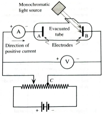
Figure 1 shows the circuit diagram to study the Photoelectric effect (PE).
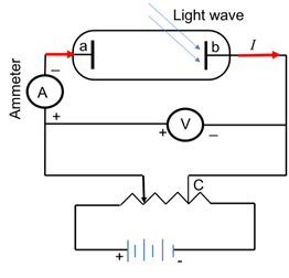
Figure 1: Set up to study photoelectric effect
A monochromatic is incident on one of the electrodes ‘b’ . Electron bonded to a metal requires a minimum energy just to leave the surface of metal is called binding energy of electron, also known as work function of the electron and denoted as
Current is flowing from positive to negative terminal of the battery (shown as red arrows in Figure 1).Therefore, the voltmeter will show the potential across electrode positive as electrons are flowing from high potential to lower potential.
Figure 2 shows the circuit diagram to study the Photoelectric effect (PE). In order to obtain the positive potentialdifference, read by voltmeter, figure 2(1) is applicable, as the electrode ‘b’ exposed to light is connected to negative terminal and other electrode ‘a’to the positive terminal of the battery. To make it more positive, one need to increase the potential of the variable battery that will make the electrode ‘a’more positive, hence will result in more positive potential across the electrodes.
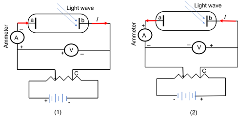
Figure 2: Set up to study photoelectric effect
In order to obtain the negative potential difference,read by voltmeter, figure 2(2) is applicable, as the electrode ‘b’ exposed to light is connected to positive terminal and other electrode ‘a’to the negative terminal of the battery.
Conclusion:
The potential across the electrodes is equal to the potential difference reading in the voltmeter.Voltmeter reading will be positive.By reversing the direction of the connection of the variable battery voltmeter can read negative potential.
Want to see more full solutions like this?
Chapter 14 Solutions
Tutorials in Introductory Physics
Additional Science Textbook Solutions
Conceptual Integrated Science
College Physics
The Cosmic Perspective (8th Edition)
Physics for Scientists and Engineers with Modern Physics
College Physics: A Strategic Approach (4th Edition)
Physics for Scientists and Engineers: A Strategic Approach, Vol. 1 (Chs 1-21) (4th Edition)


- Solve the following problems. Show and COMPLETE solutions. Draw the CIRCUIT DIAGRAM or the equivalent circuit. 1. Three lamps of resistances 5 Ω, 10 Ω and 15 Ω are connected in series. The combination is then connected to a 120-V battery. Find the equivalent resistance of the circuit, the total current in the circuit, the voltage across each lamp, the total power supplied by the battery to the circuit and the power dissipated by each lamp.arrow_forwardState which of the following statements are true and which are false. Give reasons for your answers. a) A very simple circuit consists of a battery connected across a resistor. In this circuit, the battery and the resistor are both in series and also in parallel. b) A resistor R and a capacitor C connected in series combine as = + c) Natural uranium is not radioactive until it has been processed by enrichment for use in fission reactors or bombs. d) Infrared light is more likely to cause electrons to be emitted from a metal than ultraviolet light. e) Special and General Relativity effects both matter for the operation of GPS, the former slow- ing down the clocks on GPS satellites relative to clocks on Earth and the latter speeding them up.arrow_forwardState which of the following statements are true and which are false. Give reasons for your answers. a) A very simple circuit consists of a battery connected across a resistor. In this circuit, the battery and the resistor are both in series and also in parallel. b) A resistor R and a capacitor C connected in series combine as = + 1 1 RC R c) Natural uranium is not radioactive until it has been processed by enrichment for use in fission reactors or bombs. d) Infrared light is more likely to cause electrons to be emitted from a metal than ultraviolet light. e) Special and General Relativity effects both matter for the operation of GPS, the former slow- ing down the clocks on GPS satellites relative to clocks on Earth and the latter speeding them up.arrow_forward
- II. Problem Solving. Answer the following problems. Show your complete solution for each problem on the space provided. 1. When a lightning strikes from the cloud to the ground, current as high as 25,000 amperes can occur and last for about 40µs. How much charge is transferred from the cloud to the ground during such a strike? 2. An aluminum cube has sides of length 1.80 m. What is the resistance between the two opposite faces of the cube?arrow_forwardHelp please, Show your complete (step-by-step) analysis and solution, with the appropriate equations and/or diagrams. Thank youu! 2. Given a set of 6 (six) 1.5 -V cells. Show by means of a diagram how you would connect the four cells to obtain a total voltage of: a) 3 V b) 4.5 V Indicate where a voltmeter should be connected in order to read the total voltage.arrow_forwardSuppose you have 5 circuits with each containing one resistor that is connected between the terminals of a battery. Taking note that current in the circuits is dependent on the resistance of the resistor, and the resistance on the other hand is dependent on the length and radius of the material. For which of the possibilities below is the current in the resistor smallest? (Area = Tr) %3D O a. Lo and ro O b. 2Lo and ro O c. 2Lo and 2ro O d. 4Lo and 2ro O e. Lo and roarrow_forward
- Consider the circuit shown in (Figure 1). Suppose that E = 10 V. Find the current through the resistor c. Find the potential difference across the resistor c. Find the current through the resistor d. Find the potential difference across the resistor d.arrow_forwardExplain how to find an internal resistance of a battery given two resistors, batteries, and a multimeter(s). Draw-up procedure on how to perform this experiment. Include a circuit(s) diagram to illustrate your procedure.arrow_forwardConsider the circuit configurations below, where two lightbulbs are connected to a single battery in different ways. Based on what you learned about parallel and series connections in lab, which of these two configurations would result in the light bulbs being the brightest? Fully explain your reasoning. Imagine that you are given four 100Ω resistors to build a circuit. Your challenge is to use all four of the resistors in the circuit, but the circuit must have an overall equivalent resistance of 100Ω. Is this possible? If so, draw a diagram of the circuit and explain how the connections result in a 100Ω equivalent resistance. If this is not possible, draw a diagram of a circuit involving all four resistors that has an equivalent resistance as close to 100Ω as is possible.arrow_forward
- The diagram at the right shows two identical resistors - R1 and R2 - placed in a circuit with a 12-Volt battery. Use this diagram to answer the question. The electric potential difference (voltage drop) across each resistor is ___ Volts. a. 6 b. 12 c. 24 d. ... nonsense!. The electric potential difference is dependent upon the actual resistance of the resistorsarrow_forward1. Fill in the table for this circuit. Show your work and then check your answer with PHET V R P R1 R2 R3 TOTAL 14 V 780 2 IR R3 3.3 k2 R2 1.5 k2arrow_forwardDirections: Solve the following problems below. Show your complete solution. Use the Rubric as your guide in answering. The rubric shall be used by the teacher in checking your answer. Use a separate sheet of paper for your answer 1. Compute the resistance of a hardened copper rod 2 meters long and 8 mm in diameter if the resistivity of the material is 1.756 x 10⁻⁸ ohm-meters. 2. A 0.500-meter length of wire with a cross-sectional area of 3.14 x 10⁻⁶ meters squared is found to have a resistance of 2.53 x 10⁻³ ohms. According to the resistivity chart, from what material is the wire made?arrow_forward
 College PhysicsPhysicsISBN:9781305952300Author:Raymond A. Serway, Chris VuillePublisher:Cengage Learning
 University Physics (14th Edition)PhysicsISBN:9780133969290Author:Hugh D. Young, Roger A. FreedmanPublisher:PEARSON
 Introduction To Quantum MechanicsPhysicsISBN:9781107189638Author:Griffiths, David J., Schroeter, Darrell F.Publisher:Cambridge University Press
 Physics for Scientists and EngineersPhysicsISBN:9781337553278Author:Raymond A. Serway, John W. JewettPublisher:Cengage Learning
 Lecture- Tutorials for Introductory AstronomyPhysicsISBN:9780321820464Author:Edward E. Prather, Tim P. Slater, Jeff P. Adams, Gina BrissendenPublisher:Addison-Wesley
 College Physics: A Strategic Approach (4th Editio...PhysicsISBN:9780134609034Author:Randall D. Knight (Professor Emeritus), Brian Jones, Stuart FieldPublisher:PEARSON