
Concept explainers
Videos
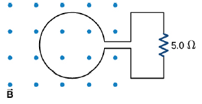
The magnetic flux through the loop shown in the accompanying figure varies with time according to

Trending nowThis is a popular solution!

Chapter 13 Solutions
University Physics Volume 2
Additional Science Textbook Solutions
Modern Physics
University Physics with Modern Physics (14th Edition)
Life in the Universe (4th Edition)
College Physics: A Strategic Approach (4th Edition)
Essential University Physics (3rd Edition)


- A circular loop of wire with a radius of 4.0 cm is in a uniform magnetic field of magnitude 0.060 T. The plane of the loop is perpendicular to the direction of the magnetic field. In a time interval of 0.50 s, the magnetic field changes to the opposite direction with a magnitude of 0.040 T. What is the magnitude of the average emf induced in the loop? (a) 0.20 V (b) 0.025 V (c) 5.0 mV (d) 1.0 mV (e) 0.20 mVarrow_forwardAn election moves through a uniform electric field E = (2.50i + 5.00j) V/m and a uniform magnetic field B = 0.400k T. Determine the acceleration of the electron when it has a velocity v = 10.0i m/s.arrow_forwardMass m = 1.00 kg is suspended vertically at rest by an insulating string connected to a circuit partially immersed in a magnetic field as in Figure P19.30. The magnetic field has magnitude Bin = 2.00 T and the length = 0.500 m. (a) Find the current I. (b) If = 115 V, find the required resistance R. Figure P19.30arrow_forward
- A circular loop of wire of resistance R = 0.500 and radius r = 8.00 cm is in a uniform magnetic field directed out of the page as in Figure P31.54. If a clockwise current of I = 2.50 mA is induced in the loop, (a) is the magnetic field increasing or decreasing in time? (b) Find the rate at which the field is changing with time. Figure P31.54arrow_forwardA rectangular coil consists of N = 100 closely wrapped turns and has dimensions a = 0.400 m and b = 0.300 m. The coil is hinged along the y axis, and its plane makes an angle = 30.0 with the x axis (Fig. P22.25). (a) What is the magnitude of the torque exerted on the coil by a uniform magnetic field B = 0.800 T directed in the positive x direction when the current is I = 1.20 A in the direction shown? (b) What is the expected direction of rotation of the coil? Figure P22.25arrow_forwardA magnetic field directed into the page changes with time according to B = 0.030 0t2 + 1.40, where B is in teslas and t is in seconds. The field has a circular cross section of radius R = 2.50 cm (see Fig. P23.28). When t = 3.00 s and r2 = 0.020 0 m, what are (a) the magnitude and (b) the direction of the electric field at point P2?arrow_forward
- A circuit consists of a conducting movable bar and a light bulb connected to two conducting rails as shown in Figure OQ23.16. An external magnetic field is directed perpendicular to the plane of the circuit. Which of the following actions will make the bulb light up? More than one statement may be correct. (a) The bar is moved to the left. (b) The bar is moved to the right. (c) The magnitude of the magnetic field is increased. (d) The magnitude of the magnetic field is decreased. (e) The bar is lifted off the rails.arrow_forwardA conducting rod of length = 35.0 cm is free to slide on two parallel conducting bars as shown in Figure P30.35. Two resistors R1 = 2.00 and R2 = 5.00 are connected across the ends of the bars to form a loop. A constant magnetic field B = 2.50 T is directed perpendicularly into the page. An external agent pulls the rod to the left with a constant speed of v = 8.00 m/s. Find (a) the currents in both resistors, (b) the total power delivered to the resistance of the circuit, and (c) the magnitude of the applied force that is needed to move the rod with this constant velocity. Figure P30.35arrow_forwardConsider the apparatus shown in Figure P30.32: a conducting bar is moved along two rails connected to an incandescent lightbulb. The whole system is immersed in a magnetic field of magnitude B = 0.400 T perpendicular and into the page. The distance between the horizontal rails is = 0.800 m. The resistance of the lightbulb is R = 48.0 , assumed to be constant. The bar and rails have negligible resistance. The bar is moved toward the right by a constant force of magnitude F = 0.600 N. We wish to find the maximum power delivered to the lightbulb. (a) Find an expression for the current in the lightbulb as a function of B, , R, and v, the speed of the bar. (b) When the maximum power is delivered to the lightbulb, what analysis model properly describes the moving bar? (c) Use the analysis model in part (b) to find a numerical value for the speed v of the bar when the maximum power is being delivered to the lightbulb. (d) Find the current in the lightbulb when maximum power is being delivered to it. (e) Using P = I2R, what is the maximum power delivered to the lightbulb? (f) What is the maximum mechanical input power delivered to the bar by the force F? (g) We have assumed the resistance of the lightbulb is constant. In reality, as the power delivered to the lightbulb increases, the filament temperature increases and the resistance increases. Does the speed found in part (c) change if the resistance increases and all other quantities are held constant? (h) If so, does the speed found in part (c) increase or decrease? If not, explain. (i) With the assumption that the resistance of the lightbulb increases as the current increases, does the power found in part (f) change? (j) If so, is the power found in part (f) larger or smaller? If not, explain. Figure P30.32arrow_forward
- A rectangular conducting loop with dimensions w = 32.0 cm and h = 78.0 cm is placed a distance a = 5.00 cm from a long, straight wire carrying current I = 7.00 A in the downward direction (Fig. P32.75). a. What is the magnitude of the magnetic flux through the loop? b. If the current in the wire is increased linearly from 7.00 A to 15.0 A in 0.230 s, what is the magnitude of the induced emf in the loop? c. What is the direction of the current that is induced in the loop during this time interval?arrow_forwardA piece of insulated wire is shaped into a figure eight as shown in Figure P23.12. For simplicity, model the two halves of the figure eight as circles. The radius of the upper circle is 5.00 cm and that of the lower circle is 9.00 cm. The wire has a uniform resistance per unit length of 3.00 Ω/m. A uniform magnetic field is applied perpendicular to the plane of the two circles, in the direction shown. The magnetic field is increasing at a constant rate of 2.00 T/s. Find (a) the magnitude and (b) the direction of the induced current in the wire. Figure P23.12arrow_forwardHow many turns must be wound on a flat, circular coil of radius 20 cm in order to produce a magnetic field of magnitude 4.0105 T at the center of the coil when the current through it is 0.85 A?arrow_forward
 Principles of Physics: A Calculus-Based TextPhysicsISBN:9781133104261Author:Raymond A. Serway, John W. JewettPublisher:Cengage Learning
 Physics for Scientists and Engineers: Foundations...PhysicsISBN:9781133939146Author:Katz, Debora M.Publisher:Cengage Learning
 College PhysicsPhysicsISBN:9781285737027Author:Raymond A. Serway, Chris VuillePublisher:Cengage Learning
 College PhysicsPhysicsISBN:9781305952300Author:Raymond A. Serway, Chris VuillePublisher:Cengage Learning
 Glencoe Physics: Principles and Problems, Student...PhysicsISBN:9780078807213Author:Paul W. ZitzewitzPublisher:Glencoe/McGraw-Hill