
Applied Statics and Strength of Materials (6th Edition)
6th Edition
ISBN: 9780133840544
Author: George F. Limbrunner, Craig D'Allaird, Leonard Spiegel
Publisher: PEARSON
expand_more
expand_more
format_list_bulleted
Concept explainers
Videos
Textbook Question
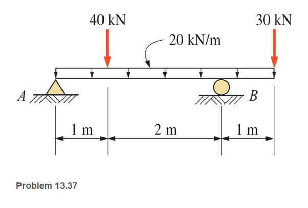
Chapter 13, Problem 13.37SP
Calculate the shear arid bending moment at points 2 m and 3.5 m from the left end of the beam shown. Use free-body diagrams.
Expert Solution & Answer
Want to see the full answer?
Check out a sample textbook solution
Students have asked these similar questions
Construct the bending Moment (M) and Shearing force diagram for the beam.
For the beam shown, the magnitude of the distributed load is Wo = 10.4 kN/m and the beam length is L = 4.8 m.
(a) derive equations for the shear force Vand the bending moment M for any location in the beam. Place the origin at point A.
(b) use the derived functions to plot the shear-force and bending-moment diagrams for the beam. Use your diagrams to determine the
maximum shear force and maximum bending moment.
Note that answers may be positive or negative. Here, "maximum" refers to the largest magnitude value, but you should enter your
shear force and bending moment with the correct sign, using the sign convention presented in Section 7.2 of the textbook. If the
magnitudes of the largest positive and largest negative values are the same, enter a positive number.
Wo
A
L
Answer:
Vmax =
kN
Mmax =
kN•m
Save for Later
Attempts: 0 of 1 used
Submit Answer
For the beam shown, the magnitude of the distributed load is wo = 11.8 kN/m and the beam length is L = 7.9 m.
(a) derive equations for the shear force Vand the bending moment M for any location in the beam. Place the origin at point A.
(b) use the derived functions to plot the shear-force and bending-moment diagrams for the beam. Use your diagrams to determine the
maximum shear force and maximum bending moment.
Note that answers may be positive or negative. Here, "maximum" refers to the largest magnitude value, but you should enter your
shear force and bending moment with the correct sign, using the sign convention presented in Section 7.2 of the textbook. If the
magnitudes of the largest positive and largest negative values are the same, enter a positive number.
Wo
A
В
L.
Answer:
Vmax =
kN
Mmax
kN•m
Chapter 13 Solutions
Applied Statics and Strength of Materials (6th Edition)
Ch. 13 - through 13.6 Calculate the reactions at points A...Ch. 13 - Calculate the reactions at points A and B for the...Ch. 13 - through 13.6 Calculate the reactions at points A...Ch. 13 - Calculate the reactions at points A and B for the...Ch. 13 - Calculate the reactions at points A and B for the...Ch. 13 - Calculate the reactions at points A and B for the...Ch. 13 - Calculate the shear and bending moment at 4 m and...Ch. 13 - Calculate the shear and bending moment at 3 ft and...Ch. 13 - Calculate the shear and bending moment at midspan...Ch. 13 - Calculate the shear and bending moment at 5 ft and...
Ch. 13 - Calculate the shear and bending moment at 5 m and...Ch. 13 - For the beams shown, draw complete shear diagrams.Ch. 13 - For the beams shown, draw complete shear diagrams.Ch. 13 - Prob. 13.14PCh. 13 - For the beams shown, draw complete shear diagrams.Ch. 13 - For the beams shown (next page), draw complete...Ch. 13 - For the beams shown (next page), draw complete...Ch. 13 - For the beams shown (next page), draw complete...Ch. 13 - For the beams shown (next page), draw complete...Ch. 13 - For the beams shown (next page), draw complete...Ch. 13 - For the beams shown, draw complete shear and...Ch. 13 - For the beams shown, draw complete shear and...Ch. 13 - For the beams shown, draw complete shear and...Ch. 13 - A moving-load system is composed of two...Ch. 13 - A moving-load system is composed of two...Ch. 13 - One of the standard truck loads used in the design...Ch. 13 - Write a computer program that will calculate the...Ch. 13 - Write a program that will calculate the shear and...Ch. 13 - Viking Consultants wishes to generate a table of...Ch. 13 - Calculate the reactions for the simple beams...Ch. 13 - Calculate the reactions for the overhanging beams...Ch. 13 - Calculate the reactions at points A and B for the...Ch. 13 - Calculate the reactions at points A and B for the...Ch. 13 - For the beams of Problem 13.33, calculate the...Ch. 13 - For the beam shown, calculate the shear and...Ch. 13 - Calculate the shear and bending moment at points 4...Ch. 13 - Calculate the shear arid bending moment at points...Ch. 13 - Calculate the shear and bending moment at points...Ch. 13 - Refer to the beam shown and draw complete shear...Ch. 13 - Refer to the beam shown and draw complete shear...Ch. 13 - Refer to the beam shown and draw complete shear...Ch. 13 - Refer to the beam shown and draw complete shear...Ch. 13 - Refer to the beam shown and draw complete shear...Ch. 13 - Refer to the beam shown and draw complete shear...Ch. 13 - Refer to the beam shown and draw complete shear...Ch. 13 - Refer to the beam shown and draw complete shear...Ch. 13 - Refer to the beam shown and draw complete shear...Ch. 13 - Refer to the indicated problem and draw complete...Ch. 13 - Refer to the indicated problem and draw complete...Ch. 13 - Refer to the indicated problem and draw complete...Ch. 13 - Refer to the indicated problem and draw complete...Ch. 13 - Refer to the indicated problem and draw complete...Ch. 13 - Refer to the indicated problem and draw complete...Ch. 13 - Refer to the indicated problem and draw complete...Ch. 13 - Refer to the indicated problem and draw complete...Ch. 13 - Refer to the indicated problem and draw complete...Ch. 13 - Refer to the indicated problem and draw complete...Ch. 13 - Refer to the indicated problem and draw complete...Ch. 13 - A two-axle roller with axles 5 m apart passes over...Ch. 13 - A moving load system with wheels at fixed...Ch. 13 - A moving-load system with wheels spaced as shown...
Knowledge Booster


Learn more about
Need a deep-dive on the concept behind this application? Look no further. Learn more about this topic, mechanical-engineering and related others by exploring similar questions and additional content below.Similar questions
- Plot the shear and moment diagrams for the beam loaded with both distributed and point loads.What is the value of the bending moment at x = 7 m?arrow_forwardWhat is the maximum intensity of moment for the beam loaded as shown? What is the degree of curve on the moment diagram at segment CD? What is the value of x, the additional point of zero shear from C?arrow_forwardDraw the Shear force and bending moment diagram for the beam as shown in figurearrow_forward
- Draw the shear force and bending moment diagrams for the beam shown in your solution sheets. Determine the maximum positive shear force in kips. Determine the maximum negative shear force in kips. Determine the maximum positive bending moment in kip-ft. Determine the maximum negative bending moment in kip-ft.* Determine the point of inflection from point C in feet.arrow_forwardDraw complete shear and bending moment diagrams. Showordinates at key points and indicate magnitude of shear andmoment. Neglect the beam weight.arrow_forwardCalculate the bending moment at points A and B for the beam shown below. 5 kN 2.5 kN/m A 1.5 m 4 marrow_forward
- Draw the shear-force and the bending-moment diagrams and specify the maximum values and their locations on the beam. only Handwitten answer needed please. do not typearrow_forwardCalculate the shear force and bending moment in each beam at sections 1-1, 2-2 and 3-3.arrow_forwardCalculate the shear force and bending moment for the simply supported beam of length 8m with the self-weight of 1OKN given below. Also draw the shear force and bending moment diagrams. 6 kN 5 kN 4 kN 1m 2m 3marrow_forward
- Construct the bending Moment (M) and Shearing force diagram for the beam. (Very detailed explanation by method of section)arrow_forwardDraw the bending moment and shear diagrams for the beam and loading shown below. Use the summation method.arrow_forwardAn overhanging beam is loaded as indicated. In order to accommodate communication cables to be installed later the beam is manufactured with two circular channels running through its length. The beam has a weight of q = 300 N/m. Calculate (a) the value and position of the maximum bending moment and sketch the relevant bending moment and shear force diagrams, (b) the position of the neutral axis, and (c) the maximum compressive and tension stress in the beam due to the bending. 2m 3 KN 3m B Bm 1 KN 100 mm 100 mm 20 mm H 30 mmarrow_forward
arrow_back_ios
SEE MORE QUESTIONS
arrow_forward_ios
Recommended textbooks for you
 Elements Of ElectromagneticsMechanical EngineeringISBN:9780190698614Author:Sadiku, Matthew N. O.Publisher:Oxford University Press
 Mechanics of Materials (10th Edition)Mechanical EngineeringISBN:9780134319650Author:Russell C. HibbelerPublisher:PEARSON
 Thermodynamics: An Engineering ApproachMechanical EngineeringISBN:9781259822674Author:Yunus A. Cengel Dr., Michael A. BolesPublisher:McGraw-Hill Education
 Control Systems EngineeringMechanical EngineeringISBN:9781118170519Author:Norman S. NisePublisher:WILEY
 Mechanics of Materials (MindTap Course List)Mechanical EngineeringISBN:9781337093347Author:Barry J. Goodno, James M. GerePublisher:Cengage Learning
 Engineering Mechanics: StaticsMechanical EngineeringISBN:9781118807330Author:James L. Meriam, L. G. Kraige, J. N. BoltonPublisher:WILEY
Elements Of Electromagnetics
Mechanical Engineering
ISBN:9780190698614
Author:Sadiku, Matthew N. O.
Publisher:Oxford University Press
Mechanics of Materials (10th Edition)
Mechanical Engineering
ISBN:9780134319650
Author:Russell C. Hibbeler
Publisher:PEARSON
Thermodynamics: An Engineering Approach
Mechanical Engineering
ISBN:9781259822674
Author:Yunus A. Cengel Dr., Michael A. Boles
Publisher:McGraw-Hill Education
Control Systems Engineering
Mechanical Engineering
ISBN:9781118170519
Author:Norman S. Nise
Publisher:WILEY
Mechanics of Materials (MindTap Course List)
Mechanical Engineering
ISBN:9781337093347
Author:Barry J. Goodno, James M. Gere
Publisher:Cengage Learning
Engineering Mechanics: Statics
Mechanical Engineering
ISBN:9781118807330
Author:James L. Meriam, L. G. Kraige, J. N. Bolton
Publisher:WILEY
Understanding Shear Force and Bending Moment Diagrams; Author: The Efficient Engineer;https://www.youtube.com/watch?v=C-FEVzI8oe8;License: Standard YouTube License, CC-BY
Bending Stress; Author: moodlemech;https://www.youtube.com/watch?v=9QIqewkE6xM;License: Standard Youtube License