
Mechanics of Materials
9th Edition
ISBN: 9780133254426
Author: Russell C. Hibbeler
Publisher: Prentice Hall
expand_more
expand_more
format_list_bulleted
Concept explainers
Videos
Textbook Question
thumb_up100%
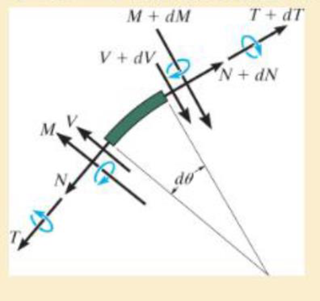
Chapter 1.2, Problem 1.30P
A differential element taken from a curved bar is shown in the figure. Show that dN/dθ = V, dV/dθ = −N, dM/dθ = −T, and dT/dθ = M.
Expert Solution & Answer
Want to see the full answer?
Check out a sample textbook solution
Students have asked these similar questions
Forces of F1=15 kN in the z direction from the B point, F2=10 kN in the z direction from the C point and F3=10 kN in the y direction act on the arm in the figure. The lengths of the arm are also given as L1=0.15 m and L2=0.16 m. The radius r in the a-a section taken over the arm is r=0.2 m and it is desired to determine the stress state at point A. The shear modulus of the sleeve material is G=65 Gpa. According to this;
WRITE YOUR RESULTS IN THE BOXES WITHOUT THE UNITS IN kPa.
a) Find the shear stress due to the shear force at point A. Response
b) Find the shear stress due to the torsional moment at point A. Response
c) Find the total shear stress at point A. Response
d) Find the normal stress due to the normal force at point A. Response
e) Find the normal stress due to the bending moment at point A. Response
f) Find the total normal stress at point A. Response
Forces of F1=8 kN in the z direction from the B point, F2=5 kN in the z direction from the C point, and F3=10 kN in the y direction act on the arm in the figure. The lengths of the arm are also given as L1=0.15 m and L2=0.16 m. The radius r in the a-a section taken over the arm is r=0.2 m and it is desired to determine the stress state at point A. slip of sleeve material module is G=75 Gpa. Accordingly,
a) Find the shear stress due to the shear force at point A.
b) Find the shear stress due to the torsional moment at point A.
c) Find the total shear stress at point A.
d) Find the normal stress due to the normal force at point A.
e) Find the normal stress due to the bending moment at point A.
f) Find the total normal stress at point A.
The steel box wrench (E=29,000ksi, v=0.32) is
loaded with a 40-lb horizontal force and a 25-lb
vertical force. Find the following for an element
located at point B on Section a-a:
24 in.
1. The non-vanishing resultant internal moments
on section a-a are which of the following?
4 in.
a. (160 i- 600 j+960 k)in · Ib
b. (-160 i+600 j+960 k ) in · lb
c. (-960 i+160 j+600 k)in - lb
d. (-960 i -160 ј-600 k)in-lb
a
e. none of the above
2. The normal and shear force components on
section a-a are:
a. V, = 65lb;V, = 40lb; N¸ = 25lb
b. V, = 0;V, =40lb; N, = 25lb
c. V, = 64;V, = 25lb; N, = 40lb
d. V, =0;V, =-40lb; N¸ = -25lb
e. none of the above
3. The non-vanishing stress components at point B are:
0̟ =1.60; t =-4.89ksi;
а.
0, =-4.89; 7 =3.60ksi;
0, = 2.50ksi; T,
d. o, = 4.91ksi; t =-4.89ksi;
b.
с.
=-4.89ksi;
е.
none of the above
4. The principal stresses at point B from most tensile to most compressive are:
O1,02,0; =4.16,–0.8,–5.76
b. o,,0,,0, =5.76,0,–4.16
а.
O1,02,0; =1.9,-2.45,-6.8
с.
d.…
Chapter 1 Solutions
Mechanics of Materials
Ch. 1.2 - In each case, explain how to find the resultant...Ch. 1.2 - Determine the resultant internal normal force,...Ch. 1.2 - Determine the resultant internal normal force,...Ch. 1.2 - Determine the resultant internal normal force,...Ch. 1.2 - Determine the resultant internal normal force,...Ch. 1.2 - Determine the resultant internal normal force,...Ch. 1.2 - Determine the resultant internal normal force,...Ch. 1.2 - The shaft is supported by a smooth thrust bearing...Ch. 1.2 - Determine the resultant internal normal and shear...Ch. 1.2 - 1-3. The beam AB is fixed to the wall and has a...
Ch. 1.2 - The shaft is supported by a smooth thrust bearing...Ch. 1.2 - 1-5. Determine the resultant internal loadings in...Ch. 1.2 - 1-6. Determine the normal force, shear force, and...Ch. 1.2 - 1-7. The cable will fail when subjected to a...Ch. 1.2 - *1-8. Determine the resultant internal loadings on...Ch. 1.2 - 1-9. Determine the resultant internal loadings on...Ch. 1.2 - The boom DF of the jib crane and the column DE...Ch. 1.2 - 1-11. The forearm and biceps support the 2-kg load...Ch. 1.2 - *1-12. The serving tray T used on an airplane is...Ch. 1.2 - The blade of the hacksaw is subjected to a...Ch. 1.2 - The blade of the hacksaw is subjected to a...Ch. 1.2 - 1-15. A 150-lb bucket is suspended from a cable on...Ch. 1.2 - *1-16. A 150-lb bucket is suspended from a cable...Ch. 1.2 - 1-17. Determine resultant internal loadings acting...Ch. 1.2 - Prob. 1.18PCh. 1.2 - Prob. 1.19PCh. 1.2 - Prob. 1.20PCh. 1.2 - Prob. 1.21PCh. 1.2 - The metal stud punch is subjected to a force of...Ch. 1.2 - Determine the resultant internal loadings acting...Ch. 1.2 - Prob. 1.24PCh. 1.2 - 1-25. Determine the resultant internal loading...Ch. 1.2 - 1-26. The shaft is supported at its ends by two...Ch. 1.2 - 1-27. The pipe assembly is subjected to a force of...Ch. 1.2 - If the drill bit jams when the brace is subjected...Ch. 1.2 - 1-29. The curved rod AD of radius r has a weight...Ch. 1.2 - A differential element taken from a curved bar is...Ch. 1.5 - In each case, determine the largest internal shear...Ch. 1.5 - Determine the largest internal normal force in the...Ch. 1.5 - Determine the internal normal force at section A...Ch. 1.5 - Prob. 1.5PPCh. 1.5 - The single-V butt joint transmits the force of 5...Ch. 1.5 - The uniform beam is supported by two rods AB and...Ch. 1.5 - Determine the average normal stress on the cross...Ch. 1.5 - Determine the average normal stress on the cross...Ch. 1.5 - If the 600-kN force acts through the centroid of...Ch. 1.5 - Determine the average normal stress at points A,...Ch. 1.5 - Determine the average normal stress in rod AB if...Ch. 1.5 - The supporting wheel on a scaffold is held in...Ch. 1.5 - Prob. 1.32PCh. 1.5 - The bar has a cross-sectional area A and is...Ch. 1.5 - 1-34. The built-up shaft consists of a pipe AB and...Ch. 1.5 - Prob. 1.35PCh. 1.5 - Prob. 1.36PCh. 1.5 - The plate has a width of 0.5 m. If the stress...Ch. 1.5 - The two members used in the construction of an...Ch. 1.5 - Prob. 1.39PCh. 1.5 - Determine the average normal stress in each of the...Ch. 1.5 - If the average normal stress in each of the...Ch. 1.5 - Determine the maximum average shear stress in pin...Ch. 1.5 - 1-43. The 150-kg bucket is suspended from end E of...Ch. 1.5 - *1-44. The 150-kg bucket is suspended from end E...Ch. 1.5 - Prob. 1.45PCh. 1.5 - 1-46. The 20-kg chandelier is suspended from the...Ch. 1.5 - Prob. 1.47PCh. 1.5 - If P = 15 kN, determine the average shear stress...Ch. 1.5 - 1-49. The joint is subjected to the axial member...Ch. 1.5 - Prob. 1.50PCh. 1.5 - Prob. 1.51PCh. 1.5 - Prob. 1.52PCh. 1.5 - Prob. 1.53PCh. 1.5 - Prob. 1.54PCh. 1.5 - The 2-Mg concrete pipe has a center of mass at...Ch. 1.5 - The 2-Mg concrete pipe has a center of mass at...Ch. 1.5 - Prob. 1.57PCh. 1.5 - Prob. 1.58PCh. 1.5 - 1-59. The jib crane is pinned at A and supports a...Ch. 1.5 - *1-60. If the shaft is subjected to an axial force...Ch. 1.5 - Prob. 1.61PCh. 1.5 - Prob. 1.62PCh. 1.5 - Prob. 1.63PCh. 1.5 - *1-64. A vertical force of P = 1500 N is applied...Ch. 1.5 - Prob. 1.65PCh. 1.5 - Determine the largest load P that can be applied...Ch. 1.5 - Prob. 1.67PCh. 1.5 - Prob. 1.68PCh. 1.7 - Rods AC and BC are used to suspend the 200-kg...Ch. 1.7 - If it is subjected to double shear, determine the...Ch. 1.7 - Determine the maximum average shear stress...Ch. 1.7 - If each of the three nails has a diameter of 4 mm...Ch. 1.7 - The strut is glued to the horizontal member at...Ch. 1.7 - Determine the maximum average shear stress...Ch. 1.7 - If the eyebolt is made of a material having a...Ch. 1.7 - If the bar assembly is made of a material having a...Ch. 1.7 - Determine the maximum force P that can be applied...Ch. 1.7 - The pin is made of a material having a failure...Ch. 1.7 - If the bolt head and the supporting bracket are...Ch. 1.7 - Six nails are used to hold the hanger at A against...Ch. 1.7 - If A and B are both made of wood and are 38 in....Ch. 1.7 - Prob. 1.70PCh. 1.7 - Prob. 1.71PCh. 1.7 - Prob. 1.72PCh. 1.7 - The steel swivel bushing in the elevator control...Ch. 1.7 - 1-74. Member B is subjected to a compressive force...Ch. 1.7 - Prob. 1.75PCh. 1.7 - Prob. 1.76PCh. 1.7 - The tension member is fastened together using two...Ch. 1.7 - 1-78. The 50-kg flowerpot is suspended from wires...Ch. 1.7 - 1-79. The 50-kg flowerpot is suspended from wires...Ch. 1.7 - *1–80. The thrust bearing consists of a circular...Ch. 1.7 - 1-81. The steel pipe is supported on the circular...Ch. 1.7 - The steel pipe is supported on the circular base...Ch. 1.7 - 1-83. The 60 mm × 60 mm oak post is supported on...Ch. 1.7 - *1-84. The frame is subjected to the load of 4 kN...Ch. 1.7 - Prob. 1.85PCh. 1.7 - The two aluminum rods support the vertical force...Ch. 1.7 - The two aluminum rods AB and AC have diameters of...Ch. 1.7 - The compound wooden beam is connected together by...Ch. 1.7 - Determine the required minimum thickness t of...Ch. 1.7 - Determine the maximum allowable load P that can be...Ch. 1.7 - Prob. 1.91PCh. 1.7 - *1-92. If the allowable hearing stress for the...Ch. 1.7 - The rods AB and CD are made of steel. Determine...Ch. 1.7 - The aluminum bracket A is used to support the...Ch. 1.7 - Prob. 1.95PCh. 1.7 - *1-96. The pin support A and roller support B of...Ch. 1 - The beam AB is pin supported at A and supported by...Ch. 1 - The long bolt passes through the 30-mm-thick...Ch. 1 - Determine the required thickness of member BC to...Ch. 1 - The circular punch B exerts a force of 2 kN on the...Ch. 1 - Determine the average punching shear stress the...Ch. 1 - The 150 mm by 150 mm block of aluminum supports a...Ch. 1 - The yoke-and-rod connection is subjected to a...Ch. 1 - The cable has a specific weight (weight/volume)...
Additional Engineering Textbook Solutions
Find more solutions based on key concepts
5.1 through 5.9
Locate the centroid of the plane area shown.
Fig. P5.1
Vector Mechanics for Engineers: Statics and Dynamics
Consider a subsonic compressible flow in cartesian coordinates where the velocity potential is given by (x,y)=V...
Fundamentals of Aerodynamics
Find the change in length of side AB.
Mechanics of Materials, 7th Edition
What parts are included in the vehicle chassis?
Automotive Technology: Principles, Diagnosis, And Service (6th Edition) (halderman Automotive Series)
Repeat Problem 4-6 except solve by the vector loop method.
DESIGN OF MACHINERY
3.3 It is known that a vertical force of 200 lb is required to remove the nail at C from the board. As the nail...
Vector Mechanics for Engineers: Statics
Knowledge Booster


Learn more about
Need a deep-dive on the concept behind this application? Look no further. Learn more about this topic, mechanical-engineering and related others by exploring similar questions and additional content below.Similar questions
- F = F cos # F = F + F F F sin 8. # tan Exampie (1):Find the two components of the force (100 X) if: 0 = 30", 120 270° as shown in figure. F = 100 N F = 100 N 6=30 0 =120° 0 =270 0 = 30 0 =60 F = 100 N lution:arrow_forwardA member is loaded with the given system of forces as shown in figure. Find the moment about A & B. Where AB = AD = 80 m, F1=35 N F2=5N, F3=39N, F4=32N, theta1=35degree , theta2= 50degree, theta3=55degree & theta4=30degree. The Moment about "A" (in Nm) = The Moment about "B" (in Nm) = The Moment about "C" (in Nm) = The Moment about "D" (in Nm) = Short Answerarrow_forwardDetermine the intensity and position of the resultant R lf two forces F1 and F3 and torque M that acts on the metal profile given as in the figure,if: F1= 2kN a=2,10m F2= 5kN b=2,10m M=24kNm c=3,10marrow_forward
- A member is loaded with force system as shown in figure. Find the Moment about A and B Where F1= 60 N, F2 =35 N, F3 =10 N, F4 =20 N, F5 =20 N, AB =130 m, Point C is in the mid of AE, CD = 40m, AE =90 m. the angle ϴ =35 (i)The moment about the point 'A' (in Nm)= MA = (ii) The moment about the point 'B' ( in Nm) = MB =arrow_forwardFor the structure shown in the figure below, assume P = 20 N, q = 23 N/m, M = 20 N.m, and L = 6 m. Determine normal force (BN) at point B in this direction . a q α A 8 10arrow_forwardwith the following modifications: Add an additional force P = 20kN acting downwards at point Barrow_forward
- 2. The component shown always breaks at point C, which is just to the right of the contact point of the roller at B. Find the internal forces in terms of shear, normal and bending to show why this is. 150 mm -250 mm- 400 N OB 125 mm 500 N 110 mm 80 N•marrow_forwardE = 150 GPa and I = 39.9(10-6) m¹. (Figure 1) Figure 40 kN-m -6 m- 1 of 1 10 kN-m Barrow_forwardShow the zero force members on the figure (label them on the figure and list them on the side). (Note: you don't have to solve the entire structure) D E 60 kips В F A M L K J G Н 180 kips 120 kipsarrow_forward
- The shaft is supported at its ends by two bearings A and B and is subjected to the forces applied to the pulleys fixed to the shaft. ( Figure 1) The T₁ = 410-N forces act in the -z direction and the 200-N and 80-N forces act in the +y direction. The journal bearings at A and B exert only y and z components of force on the shaft. Figure X 200 mm 300 mm 150 mm 150 mm 200 mm D 400 mm B 200 N 200 N Z 80 N 80 N 1 of 1 > ▾ Part B ▾ Determine the resultant shear force in the y direction on the cross section at C. Express your answer to three significant figures and include appropriate units. (Vc), = 245.71 ▾ Part C Submit Previous Answers Request Answer * Incorrect; Try Again; 4 attempts remaining Submit (Vc), = Value Part D Determine the resultant shear force in the direction on the cross section at C. Express your answer to three significant figures and include appropriate units. T= HA Submit Part E ריהם Determine the resultant torque on the cross section at C Express your answer to three…arrow_forwardUse the method of SECTIONS to find the true magnitude and direction in bar HG of the truss shown below in Fig 3.5 -500lb -100lb A 45° -200lb H -100lb 2 B -200lb -200lb MAGNITUDE AND DIRECTION OF SUPPORTS -500lb H -100lb 45° 2¹ C2D 2¹ Fig 3.5. -200lb -100lb LI 2 B 2₁ 2₁ D 2₁ Earrow_forwardFind The Horizontal and Vertical Component For Force (F) shown in figure. Q=275 N F=210 N 5 3 4 45° P=355 Narrow_forward
arrow_back_ios
SEE MORE QUESTIONS
arrow_forward_ios
Recommended textbooks for you
 Mechanics of Materials (MindTap Course List)Mechanical EngineeringISBN:9781337093347Author:Barry J. Goodno, James M. GerePublisher:Cengage Learning
Mechanics of Materials (MindTap Course List)
Mechanical Engineering
ISBN:9781337093347
Author:Barry J. Goodno, James M. Gere
Publisher:Cengage Learning
Types Of loads - Engineering Mechanics | Abhishek Explained; Author: Prime Course;https://www.youtube.com/watch?v=4JVoL9wb5yM;License: Standard YouTube License, CC-BY