
Videos
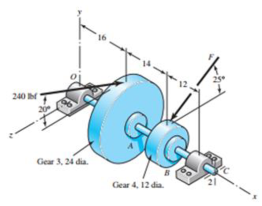
A gear-reduction unit uses the countershaft depicted in the figure. Find the two bearing reactions. The beatings are to be angular-contact ball bearings, having a desired life of 50 kh when used at 300 rev/min. Use 1.2 for the application factor and a reliability goal for the bearing pair of 0.96, assuming distribution data from manufacturer 2 in Table 11-6. Select the bearings from Table 11-2.
Problem 11-34
Dimensions in inches.
The reaction load at point O
The reaction load at point C
The bore diameter of angular contact ball bearing at point O.
The bore diameter of angular contact ball bearing at point C.
Answer to Problem 34P
The reaction load at point O is
The reaction load at point C is
The bore diameter of angular contact ball bearing at point O is 17 mm.
The bore diameter of angular contact ball bearing at point C is 35 mm.
Explanation of Solution
Write the expression for net force in y direction at point A.
Here, net force in y direction at point A is
Write the expression for net force in z direction at point A.
Write the expression for net force in y direction at point B.
Here, net force in y direction at point B is
Write the expression for net force in z direction at point B.
Here, net force in y direction at point B is
Write the expression for net torque on shaft.
Here, radius of gear at point A is
Write the expression for moment equilibrium in
Here, the moment is
Write the expression for moment equilibrium in
Here, the reaction force at C in z direction is
Write the expression for static force equilibrium in
Here, the force is
Write the expression for static force equilibrium in
Here, the force is
Write the expression for resultant force at point O.
Here, the resultant force at point O is
Write the expression for resultant force at point C.
Here, the resultant force at point C is
Write the expression for desired reliability.
Here, the desired reliability is
Write the expression for multiple of dating life.
Here, the multiple of rating life is
Write the expression for catalogue load rating at point O.
Here the catalogue load rating is
Write the expression for catalogue load rating at point C.
Here the catalogue load rating is
Conclusion:
Substitute
Substitute
Substitute
Substitute
Substitute
Substitute
Substitute
Substitute
Substitute
Substitute
Substitute
Substitute
Thus the reaction load at point O is
Substitute
Thus the reaction load at point C is
Substitute 0.96 for
Substitute
Refer to Table 11-6 “Typical Weibull Parameters for Two Manufacturers” to obtain values of
Substitute
Refer to Table 11-2 “Dimensions and Load Ratings for Single-Row 02-Series Deep-Groove and Angular-Contact Ball Bearing” to obtain 17 mm bore size angular contact ball bearing corresponding to
Thus the Bore diameter of angular contact ball bearing at point O is 17 mm.
Substitute
Refer to Table 11-2 “Dimensions and Load Ratings for Single-Row 02-Series Deep-Groove and Angular-Contact Ball Bearing” to obtain 35 mm bore size angular contact ball bearing corresponding to
Thus Bore diameter of angular contact ball bearing at point C is 35 mm.
Want to see more full solutions like this?
Chapter 11 Solutions
Shigley's Mechanical Engineering Design (McGraw-Hill Series in Mechanical Engineering)


- The design load on a ball bearing is 413 lbf and an application factor of 1.2 is appro- priate. The speed of the shaft is to be 300 rev/min, the life to be 30 kh with a reliability of 0.99. What is the C10 catalog entry to be sought (or exceeded) when searching for a deep-groove bearing in a manufacturer's catalog on the basis of 106 revolutions for rat- ing life? The Weibull parameters are xo = 0.02, (0 – xo) = 4.439, and b = 1.483. %3Darrow_forwardProblem 6 An 02-series single-row deep-groove ball bearing with an 80 mm bore is loaded with a 5-kN axial load and a 9-KN radial load. The bearing has the basic dynamic load rating C₁0 of 70.2kN and basic static load rating Co of 45kN. The outer ring rotates at 500 rev/min. Use the Weibull parameters for Manufacturer 2: x₁=0.02; ; b=1.483. 0 = 4.459 and the application factor of 1.0. (a) Determine the equivalent radial load that will be experienced by this particular bearing. (b) Determine whether this bearing should be expected to carry this load with a 95 percent reliability for 15 kh.arrow_forwardFor the geared countershaft with an overhanging pinion at C, the force on gear A is FA = 600 Ibf, and the shaft is to run at a speed of 420 rev/min. Consider an application factor of 1.2, a desired life of 40 kh, and combined reliability goal of 0.95 Select and specify the bearing required a) An angular contact ball bearing for mounting at O and b) A straight roller bearing for mounting at B Gear 3 24 dia. Gear 4 10 dia. 20arrow_forward
- Problem 13.049 - Bearing Reactions for Beveled Gears The figure shows a 16T 20° straight bevel pinion driving a 32 T gear and the location of the bearing centerlines. Pinion shaft a receives 2 hp at 200 rev/min. Determine the bearing reactions at A if it is to take both radial and thrust loads. Problem 13-43 Dimensions in inches. The bearing reaction due to radial load FA, radial is | B 4 Ibf and the bearing reaction due to thrust load FA, thrust is Ibf.arrow_forwardA machine operated for 8 hrs a day under light impact is fitted with a shaft with bearings fitted at A and B. The shaft requires a design life of 25 000 hours at a speed of 475 rpm. The load on the shaft is indicated in the figure. The reliability goal for the shaft is 95%. Determine the following: Multiple of rating life required (Xp) b. а. Catalogue rating (C10) Specify a suitable 02-series deep groove ball bearing d. c. The actual shaft reliability The maximum speed that the bearing should be applied at to ensure a life of 40 000 hrs at the same reliability. е. 3000 N 5000 N 500 mm 450 mm 600 mm A Вarrow_forwardA cylinder with a nominal 2.5 in ID, a 4.0 in OD, and a 3.0 in length is to be mated with a solid shaft with a nominal 2.5 in diameter. A medium drive fit is desired (as defined in Table 7-9). The cylinder and shaft are made from steel, with Sy = 100 kpsi and E = 30 Mpsi. The coefficient of friction for the steel interface is 0.7. a. Specify the maximum and minimum allowable diameters for both the cylinder hole and the shaft. b. Determine the torque that can be transmitted through this joint, assuming the shaft and cylinder are both manufactured within their tolerances such that the minimum interference is achieved. c. Suppose the shaft and cylinder are both manufactured within their tolerances such that the maximum interference is achieved. Check for yielding of the cylinder at its inner radius by finding the following: i. The pressure at the interface ii. The tangential and radial stresses in the cylinder, at its inner radius. iii. The factor of safety for static yielding of the…arrow_forward
- 3. Figure 4 shows a simplified schematic of the drive system of joint 4 of the PUMA 560. The torsional stiffness of the couplings is 200 Nt-m/radian each, that of the shaft is 400 Nt-m/radian, and each of the reduction gear pairs has been measured to have output stiffness of 2000 Nt-m/radian with its input gears fixed. Both the first and second reductions have n=4. Assuming the structure and bearing are perfectly rigid, a) What is the effective stiffness of gear 1 if the electric motor's shaft is locked? b) What is the effective stiffness of gear 3 if the electric motor's shaft is locked? c) What is the stiffness of the joint (i.e., when the motor's shaft is locked)? In other words, find out the effective stiffness of the output gear 4. - Electric motor -#1 Coupling Connecting rod #2 Coupling -#1 Gear 42 Gear #3 Gear - #4 Gear Figure 4: Simplified version of the driven train of joint 4 of PUMA 560.arrow_forward5. Design a sleeve coupling for the transmission of 12 kW at 300 rpm by two connected steel shafts. Take service factor KS 1.25. The sleeve is made of CI. The key and the shaft are made of the same material. Allowable stress: Shear stresses in key and shaft 50 MPa Crushing stress in key= 100 MPa Shear stress in CI sleeve = 10 MPaarrow_forwardUse the general shaft layout given and determine critical diameters of the shaft based on infinite fatigue life with a design factor of 1.5. Check for yielding. Check the slopes at the bearings for satisfaction of the recommended limits in Table 7-2. Assume that the deflections for the pulleys are not likely to be critical. 10 in 500 lbf 75 lbf 8-in dia. Bearing at O 10.0" 500 lb d 75 lb Material 1040 Q and T 18 in Use the following shaft layout assuming a pulley transmits torque through a key and keyseat at location A to another pulley at location B. Assume the tensions in the belt at pulley Bare T₁ and T2, where T₁ is 15% of T2. NOTE: This is a multi-part question. Once an answer is submitted, you will be unable to return to this part. 10-in dia. 12 in T₂ 8.0⁰ T₁ 18.0" 10.0" I B pulley diameter = 8.0" Sut 113 kpsi T2 T1 pulley diameter = 10.0" Sy 86 kpsi 12.0" Bearing at C Using the DE-Goodman criteria and a design factor of 1.5, calculate the diameter based on the shaft's loadings…arrow_forward
- Problem 4. A 16-tooth 240 Bhn steel spur pinion having a pressure angle of 20° and rotating at 720 rev/min drives a 28-tooth 240 Bhn steel gear having a 2.5 -in face and a diametral pitch of 5 teeth/in. Find the factor of safety of this drive based on bending strength if 17.5 hp is transmitted. Use Ko=Ks=1, Km=1.6 and Qv=7.arrow_forwardA shaft rotating at constant speed is subjected to variable load. The bearings supporting the shaftare subjected to stationary equivalent radial load of 3 kN for 10 per cent of time, 2 kN for 20 percent of time, 1 kN for 30 per cent of time and no load for remaining time of cycle. If the total lifeexpected for the bearing is 20 × 106revolutions at 95 per cent reliability, calculate dynamic loadrating of the ball bearing.arrow_forwardA stone crusher machine working 8 hours a day is driven by an electric motor with a narrow-V belt-pulley mechanism. The transmitted power is P = 18.5 kW, the speed of the motor is n1 = 1450 RPM, and the required rotational speed for the stone machine is n2 = 690D / d. Sizing of the narrow-V belt-pulley mechanism is required according to the given. Recommended value for the axle spacing a = k. (dw1 + dw2) k = 0.9arrow_forward
 Elements Of ElectromagneticsMechanical EngineeringISBN:9780190698614Author:Sadiku, Matthew N. O.Publisher:Oxford University Press
 Mechanics of Materials (10th Edition)Mechanical EngineeringISBN:9780134319650Author:Russell C. HibbelerPublisher:PEARSON
 Thermodynamics: An Engineering ApproachMechanical EngineeringISBN:9781259822674Author:Yunus A. Cengel Dr., Michael A. BolesPublisher:McGraw-Hill Education
 Control Systems EngineeringMechanical EngineeringISBN:9781118170519Author:Norman S. NisePublisher:WILEY
 Mechanics of Materials (MindTap Course List)Mechanical EngineeringISBN:9781337093347Author:Barry J. Goodno, James M. GerePublisher:Cengage Learning
 Engineering Mechanics: StaticsMechanical EngineeringISBN:9781118807330Author:James L. Meriam, L. G. Kraige, J. N. BoltonPublisher:WILEY