
Concept explainers
Videos
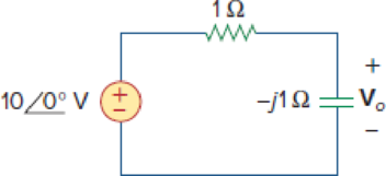
The voltage Vo across the capacitor in Fig. 10.43 is:


Figure 10.43
For Review Question 10.1.
Choose the correct option to find the voltage
Answer to Problem 1RQ
The correct option from the given choices is
Explanation of Solution
Given data:
Refer to Figure 10.43 in the textbook for circuit analysis.
Calculation:
From Figure 10.43, write the expression for voltage
Reduce the equation as follows.
Hence, the voltage across the capacitor is
Conclusion:
Thus, the correct option from the given choices is
Want to see more full solutions like this?
Chapter 10 Solutions
Fundamentals of Electric Circuits
Additional Engineering Textbook Solutions
Introductory Circuit Analysis (13th Edition)
Electrical Engineering: Principles & Applications (7th Edition)
Electronics Fundamentals: Circuits, Devices & Applications
Basic Engineering Circuit Analysis
Electric Motors and Control Systems
ANALYSIS+DESIGN OF LINEAR CIRCUITS(LL)


- 10.25 For the following RC circuit: + e - 56 μF 22 V 7 kl a) Determine the time constant of the circuit when the switch is thrown into position 1. b) Find the mathematical expression for the voltage across the capacitor and the current after the switch is thrown into position 1. C) Determine the magnitude of the voltage vC and the current iC the instant the switch is thrown into position 2 at t=1s. d) Determine the mathematical expression for the voltage vC and the current iC for the discharge phase e) Plot the waveforms of vC and iC for the period of time extending from 0 to 2 seconds from when the switch was thrown into position 1arrow_forward10. SERPSE10 27.4.OP.021. Consider a series RC circuit as in the figure below for which R=4.00 MQ, C= 4.00 uF, and - 34.0 V. DETAILS (a) Find the time constant of the circuit. R (b) What is the maximum charge on the capacitor after the switch is thrown closed? Need Help? Q (c) Find the current in the resistor 10.0 s after the switch is closed. LA Wicht MY NOTES ASK YOUR TEACHEarrow_forward10.43 The capacitor is initially charged to 10 volts with the polarity shown. 1.5 kn R68 kn vc c22uF 10V 1=4 mA a) Write the mathematical expression for the voltage vC and the current iC when the switch is closed b) Sketch the waveforms vC and icarrow_forward
- C.) A part of a radio tuning circuit has an inductance of 0.2microH and a variablecapacitor. If the circuit is to tune at 102.7MHz FM frequency, determine the value ofthe capacitor needed to tune this circuit.arrow_forwardA constant voltage at a frequency of 1 MHz is applied to an inductor in series with a variable 0 capacitor. When the capacitor is set 500 pF, the current has its maximum value while it is reduced to one-half when the capacitance is 600 pF. Find the resistance, inductance, Q-factor of the inductor. Ans:50.66 µH, 30.62 Ohms,10.4 1arrow_forwardCalculate the high cutoff frequency WH . note:Determine the capacitance values yourself.arrow_forward
- 3. You are given voltage across capacitor in the above circuit for various time points. Which of the following plots would produce linear curve? In(Vo)vs.time In(Vo)us.ln(time) In (Vo-V) vs. time In (Vo-V) vs. In(time)arrow_forwardQ10.Using diagrams, explain the correctness of the relation ICEO = (β + 1)ICBO.arrow_forwardExample 2 A parallel plate capacitor transducer has plate area of 500 mm2 and air separation of 0.5 mm is used to measure displacement of an object coupled to one plate of capacitor. Find capacitance when displacement is 0.1 mm. Also find sensitivity of transducer. Assume E = 8..85 .x 10-12 F/m.arrow_forward
- The voltage across 20 micro-farad capacitor varies with time as given by vc = (10.75 - 1.5e -1000t) volts. What is the current through capacitor after 1 millisecond? 0.023 0.011 A 0.033 A 0.013 Aarrow_forwardFor the circuit of fig.10.51. If is= 5cos10t A. use suitable complex source replacement to obtain a steady-state expression for iL (t) please help me with this assignment and kindly show you're solutions. thanks.arrow_forward10. A radio can tune over the frequency range of a portion of MW broadcast band: (800 kHz to 1200 kHz). If its LC circuit has an effective inductance of 200 µH, what must be the range of its variable capacitor? [Hint: For tuning, the natural frequency i.e., the frequency of free oscillations of the LC circuit should be equal to the frequency of the radiowave.]arrow_forward
 Introductory Circuit Analysis (13th Edition)Electrical EngineeringISBN:9780133923605Author:Robert L. BoylestadPublisher:PEARSON
 Delmar's Standard Textbook Of ElectricityElectrical EngineeringISBN:9781337900348Author:Stephen L. HermanPublisher:Cengage Learning
 Programmable Logic ControllersElectrical EngineeringISBN:9780073373843Author:Frank D. PetruzellaPublisher:McGraw-Hill Education
 Fundamentals of Electric CircuitsElectrical EngineeringISBN:9780078028229Author:Charles K Alexander, Matthew SadikuPublisher:McGraw-Hill Education
 Electric Circuits. (11th Edition)Electrical EngineeringISBN:9780134746968Author:James W. Nilsson, Susan RiedelPublisher:PEARSON
 Engineering ElectromagneticsElectrical EngineeringISBN:9780078028151Author:Hayt, William H. (william Hart), Jr, BUCK, John A.Publisher:Mcgraw-hill Education,