
Concept explainers
Videos
The currents
Answer to Problem 10.69P
Explanation of Solution
Given:
Calculation:
The given circuit is,
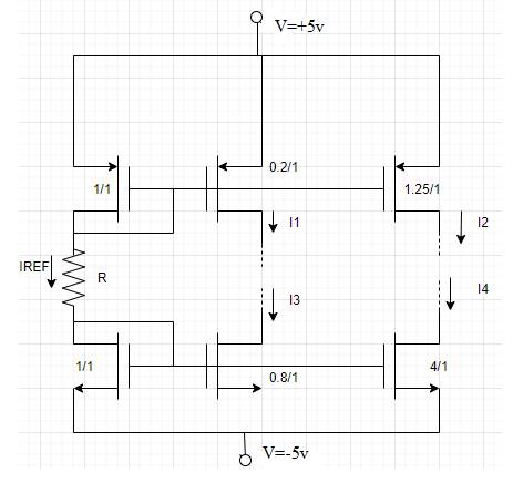
According to the circuit reference current
And
Now substitute the given values in equation (1) and equation (2),
On comparing equation (3) and equation (4),
Now reference current expression is,
Now compare equation (3) and equation (6)
Solve the above expression by quadratic degree method,
Consider
Calculate reference current,
Now calculate current
Conclusion:
Want to see more full solutions like this?
Chapter 10 Solutions
Microelectronics: Circuit Analysis and Design


- Please answer both subpart for like this please Asap for like..arrow_forwardFor the circuit given in figure below draw the collector characteristic curves for IB = 50,150 and 250 micro amperes on the same grapharrow_forwardFrom the circuit below, determine the output peak voltage Vm ? Np:Ns 6:1 Vp 120 Vac out 60 Hz DA R = 200 2 O Ovpeak O 169.71Vpeak O 28.28Vpeak O 1018.23Vpeakarrow_forward
- Draw the waveform of the given clipper circuit and determine the following: a.) At 0V, what is the output voltage?b.) At +20V, what is the output voltage?c.) At -5V, what is the output voltage?arrow_forward3. A step-up chopper is to provide a 48V across a 12Y~load from a 12V d.c. supply. The chopper inductance is 10tzH and the chopper frequency is 100kHz. Determine the duty cycle required and the variation of battery current during switching, and the maximum and minimum battery currentsarrow_forwardDesign the power supply using diode components. This power supply sholud have 2 outputs. 12Vdc and 5Vdc. Input 240 Vac Supply i. Draw the circuit diagram ii. Bill of material/components that will be used iii. Teh output waveform for each stagearrow_forward
- Problem5: For the common base circuit shown in figure find L and Vca. Assume transistor is Silicon.(a=0.98) IE Ic RE= 1.5 kQ Rc= 1.2 k VEE =8 V Vcc= 18 Varrow_forwardSketch the voltage signal v=3cos(5t -20°). Also, determine the peak value, peak-to-peak value, frequency and phasearrow_forwardSolve for the collector voltagearrow_forward
- The positive peak value of output waveform for the given circuit diagram is.. . (VPP of input is 14 V, Bias voltage is 4 V, Diode is silicon) R1 I D, VIN VOut VELAS Earrow_forwardThe circuit is shown below, Vin is the sinusoidal waveform with magnitude 5V and frequency is 100 Hz, R = 1 k, C = 1 uE, the chip is supplied by + 12 V source. a) What is the waveform of Yout? b) Calculate the magnitude of Vo c) If Vin is triangle waveform, what is the output waveform? -Vout , if Vin is triangle waveform with magnitude of 5 V (peak-to-peak value is 10 V) and frequency is 10 kHz, calculate waveform of you and the magnitude of I/?arrow_forwardThe positive peak value of output waveform for the given circuit diagram is.. (VPP of input is 18 V, Bias voltage is 3 V, Diode is germanium) R: D, VIN VouUT VaASarrow_forward
 Introductory Circuit Analysis (13th Edition)Electrical EngineeringISBN:9780133923605Author:Robert L. BoylestadPublisher:PEARSON
 Delmar's Standard Textbook Of ElectricityElectrical EngineeringISBN:9781337900348Author:Stephen L. HermanPublisher:Cengage Learning
 Programmable Logic ControllersElectrical EngineeringISBN:9780073373843Author:Frank D. PetruzellaPublisher:McGraw-Hill Education
 Fundamentals of Electric CircuitsElectrical EngineeringISBN:9780078028229Author:Charles K Alexander, Matthew SadikuPublisher:McGraw-Hill Education
 Electric Circuits. (11th Edition)Electrical EngineeringISBN:9780134746968Author:James W. Nilsson, Susan RiedelPublisher:PEARSON
 Engineering ElectromagneticsElectrical EngineeringISBN:9780078028151Author:Hayt, William H. (william Hart), Jr, BUCK, John A.Publisher:Mcgraw-hill Education,