
Basic Engineering Circuit Analysis
11th Edition
ISBN: 9781118539293
Author: J. David Irwin, R. Mark Nelms
Publisher: WILEY
expand_more
expand_more
format_list_bulleted
Concept explainers
Videos
Textbook Question
thumb_up100%
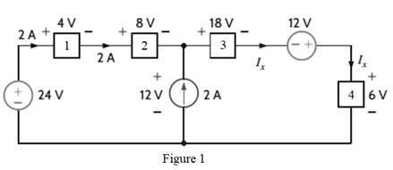
Chapter 1, Problem 41P
Find
Expert Solution & Answer
Want to see the full answer?
Check out a sample textbook solution
Students have asked these similar questions
solve for the following dc quantities: d. V C(Q1) . e. V B(Q2) . f. V E(Q2) . g. I E(Q2) . h. V C(Q2) .
An element has voltage v and current i as shown in the picture. The voltage and current relate as seen in the data table. Using the laws of Superposition and Homogeneity, determine if the element is linear:
Determine the differential equation governing the voltage across the current source at t20.
C1
1F
t=0
(L1
31H
1
R3
C2
R4
2A
0.50
E1F
20
H
Chapter 1 Solutions
Basic Engineering Circuit Analysis
Ch. 1 - If the current in an electric conductor is 2.4 A,...Ch. 1 - Determine the time interval required for a 12�A...Ch. 1 - A lightning bolt carrying 30,000 A lasts for 50...Ch. 1 - If a 12-V battery delivers 100 J in 5 s, find (a)...Ch. 1 - The current in a conductor is 1.5 A. How many...Ch. 1 - If 60 C of charge pass through an electric...Ch. 1 - Determine the number of coulombs of charge...Ch. 1 - Five coulombs of charge pass through the element...Ch. 1 - The current that enters an element is shown in...Ch. 1 - The charge entering the positive terminal of an...
Ch. 1 - The charge entering the positive terminal of an...Ch. 1 - Prob. 12PCh. 1 - The power absorbed by the BOX in Fig. Pl. 13 is...Ch. 1 - The power absorbed by the BOX in Fig. Pl. 14 is...Ch. 1 - The energy absorbed by the BOX in Fig. P1.15 is...Ch. 1 - The charge that enters the BOX in Fig. P1.16 is...Ch. 1 - The energy absorbed by the BOX in Fig. Pl. 17 is...Ch. 1 - The charge entering the upper terminal of the BOX...Ch. 1 - The energy absorbed by the BOX in Fig. Pl. 19 is...Ch. 1 - Determine the amount of power absorbed or supplied...Ch. 1 - Calculate the power absorbed by element A in Fig....Ch. 1 - Calculate the power supplied by element A in Fig....Ch. 1 - Element A in the diagram in Fig. PI .23 absorbs 30...Ch. 1 - Element B in the diagram in Fig. P1.24 supplies 60...Ch. 1 - Element B in the diagram in Fig. PI .25 supplies...Ch. 1 - Element B in the diagram in Fig. Pl.26 supplies 72...Ch. 1 - (a) In Fig. Pl.27 (a), P1=36W. Is element 2...Ch. 1 - Two elements are connected in series, as shown in...Ch. 1 - Element 2 in Fig. Pl.29 absorbed 32W. Find the...Ch. 1 - Choose Is such that the power absorbed by element...Ch. 1 - Find the power that is absorbed or supplied by the...Ch. 1 - Find the power that is absorbed or supplied by the...Ch. 1 - Compute the power that is absorbed or supplied by...Ch. 1 - Find the power that is absorbed or supplied by...Ch. 1 - Find Ix in the network in Fig. P1.35.Ch. 1 - Prob. 36PCh. 1 - Find the power absorbed or supplied by element 1...Ch. 1 - Find the power absorbed or supplied by element 3...Ch. 1 - Find the power absorbed or supplied by element 1...Ch. 1 - Find Vx in the network in Fig. P1.40 using...Ch. 1 - Find Ix in the circuit in Fig. P1.41 using...Ch. 1 - Is the source Vs in the network in Fig. P1.42...Ch. 1 - Find I0 in the network in Fig. P1.43 using...Ch. 1 - Calculate the power absorbed by each element in...Ch. 1 - Calculate the power absorbed by each element in...Ch. 1 - In the circuit in Fig. P1.46, element 1 absorbs 40...
Knowledge Booster


Learn more about
Need a deep-dive on the concept behind this application? Look no further. Learn more about this topic, electrical-engineering and related others by exploring similar questions and additional content below.Similar questions
- Find ? in the circuit shown below under dc conditionsarrow_forwardQ1) asks to show that the d.c. bias current to the differential pairs is Iccs = 0.6 mA But you used iccs= 0.6 to answer the question. isnt the question asking you to prove that without using iccs= 0.6 it gives you to answer the question?arrow_forwardFind the steady-state currents I1 and I2 for the network in Fig. (a) I1(b) I2arrow_forward
arrow_back_ios
SEE MORE QUESTIONS
arrow_forward_ios
Recommended textbooks for you
 Introductory Circuit Analysis (13th Edition)Electrical EngineeringISBN:9780133923605Author:Robert L. BoylestadPublisher:PEARSON
 Delmar's Standard Textbook Of ElectricityElectrical EngineeringISBN:9781337900348Author:Stephen L. HermanPublisher:Cengage Learning
 Programmable Logic ControllersElectrical EngineeringISBN:9780073373843Author:Frank D. PetruzellaPublisher:McGraw-Hill Education
 Fundamentals of Electric CircuitsElectrical EngineeringISBN:9780078028229Author:Charles K Alexander, Matthew SadikuPublisher:McGraw-Hill Education
 Electric Circuits. (11th Edition)Electrical EngineeringISBN:9780134746968Author:James W. Nilsson, Susan RiedelPublisher:PEARSON
 Engineering ElectromagneticsElectrical EngineeringISBN:9780078028151Author:Hayt, William H. (william Hart), Jr, BUCK, John A.Publisher:Mcgraw-hill Education,
Introductory Circuit Analysis (13th Edition)
Electrical Engineering
ISBN:9780133923605
Author:Robert L. Boylestad
Publisher:PEARSON
Delmar's Standard Textbook Of Electricity
Electrical Engineering
ISBN:9781337900348
Author:Stephen L. Herman
Publisher:Cengage Learning
Programmable Logic Controllers
Electrical Engineering
ISBN:9780073373843
Author:Frank D. Petruzella
Publisher:McGraw-Hill Education
Fundamentals of Electric Circuits
Electrical Engineering
ISBN:9780078028229
Author:Charles K Alexander, Matthew Sadiku
Publisher:McGraw-Hill Education
Electric Circuits. (11th Edition)
Electrical Engineering
ISBN:9780134746968
Author:James W. Nilsson, Susan Riedel
Publisher:PEARSON
Engineering Electromagnetics
Electrical Engineering
ISBN:9780078028151
Author:Hayt, William H. (william Hart), Jr, BUCK, John A.
Publisher:Mcgraw-hill Education,
Kirchhoff's Rules of Electrical Circuits; Author: Flipping Physics;https://www.youtube.com/watch?v=d0O-KUKP4nM;License: Standard YouTube License, CC-BY