
Videos
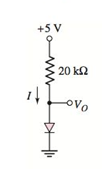
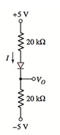
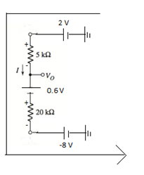
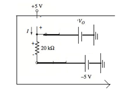
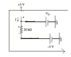
Find I and
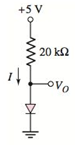
(a).
The values of
Answer to Problem 1.47P
For
For
Explanation of Solution
Given Information:
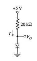
The given circuit is shown below.
Two values of
Calculation:
For
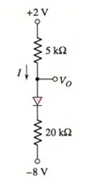
The given circuit diagram is:
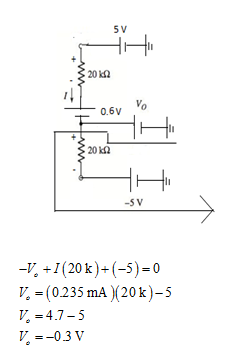
Assuming the diode is in ON state and the modified circuit is:
Applying Kirchhoff’s voltage law:
The direction of current is from p-region to n-region of diode. Hence, the assumption is correct.
Applying Kirchhoff’s voltage law:
For
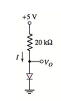
The given circuit diagram is:
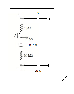
Assuming the diode is in ON state and the modified circuit is:
Applying Kirchhoff’s voltage law:
The direction of current is from p-region to n-region of diode. Hence, the assumption is correct.
Applying Kirchhoff’s voltage law:
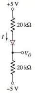
(b).
The values of
Answer to Problem 1.47P
For
For
Explanation of Solution
Given Information:
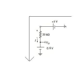
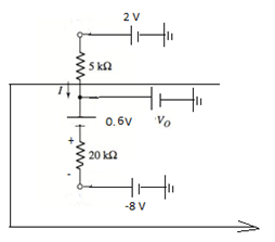
The given circuit is shown below.
Two values of
Calculation:
For
The given circuit diagram is:
Assuming the diode is in ON state and the modified circuit is:
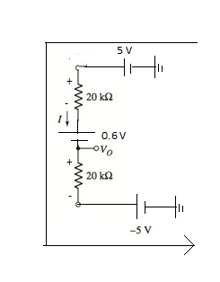
Applying Kirchhoff’s voltage law:
The direction of current is from p-region to n-region of diode. Hence, the assumption is correct.
Applying Kirchhoff’s voltage law in the following circuit:
For
The given circuit diagram is:
Assuming the diode is in ON state and the modified circuit is:
Applying Kirchhoff’s voltage law:
The direction of current is from p-region to n-region of diode. Hence, the assumption is correct.
Applying Kirchhoff’s voltage law in the following circuit:
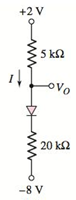
(c)
The values of
Answer to Problem 1.47P
For
For
Explanation of Solution
Given Information:
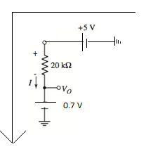
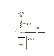
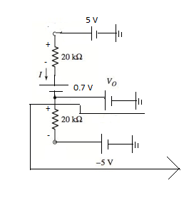
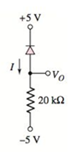
The given circuit is shown below.
Two values of
Calculation:
For
The given circuit diagram is:
Assuming the diode is in ON state and the modified circuit is :
Applying Kirchhoff’s voltage law:
The direction of current is from p-region to n-region of diode. Hence, the assumption is correct.
Applying Kirchhoff’s voltage law in the following circuit:
For
The given circuit diagram is:
Assuming the diode is in ON state and the modified circuit is:
Applying Kirchhoff’s voltage law:
The direction of current is from p-region to n-region of diode. Hence, the assumption is correct.
Applying Kirchhoff’s voltage law in the following circuit:
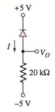
(d).
The values of
Answer to Problem 1.47P
For
For
Explanation of Solution
Given Information:
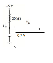
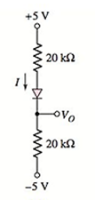
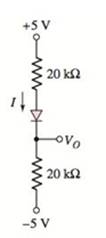
The given circuit is shown below.
Two values of
Calculation:
For
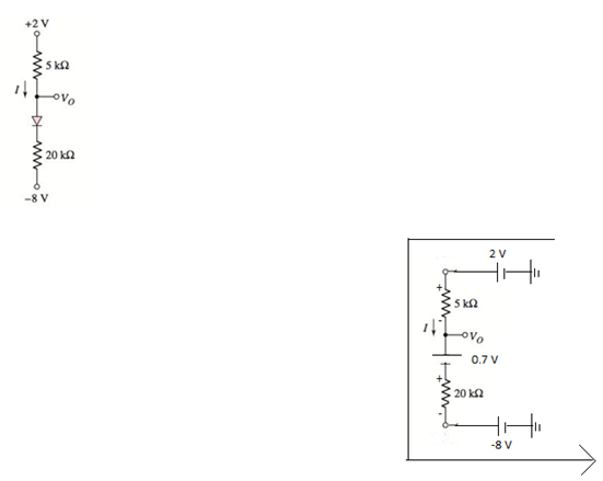
The given circuit diagram is:
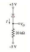
Assuming the diode is in OFF state. Hence, the modified circuit is:

From the circuit:
In this circuit, the diode is reverse biased, so it is in OFF mode. Hence, the assumption is correct and the value of current
Applying Kirchhoff’s voltage law in the following circuit:
For
The given circuit diagram is:
Assuming the diode is in OFF state. Hence, the modified circuit is:
From the circuit:
In this circuit, the diode is reverse biased, so it is in OFF mode. Hence, the assumption is correct and the value of current
Applying Kirchhoff’s voltage law in the following circuit:
Want to see more full solutions like this?
Chapter 1 Solutions
Microelectronics: Circuit Analysis and Design
Additional Engineering Textbook Solutions
Basic Engineering Circuit Analysis
Engineering Electromagnetics
Principles and Applications of Electrical Engineering
Electric Circuits. (11th Edition)
Electronics Fundamentals: Circuits, Devices & Applications
Electric machinery fundamentals


- 1) Solve the following values in figure 1.0. a) Total capacitance, Ct b) Total charge, Qt c) Individual charge of (a) C1 (b) C2 (c) C3 FIGURE 1.0 C3 100 uF V1 1V C1 20 uF C2 15 uF (+1arrow_forwardFor the network shown in figure (3), if the switch is closed for 2usec and then opened for Susec, find mathematical expressions for vi and in of both periods of time and then plot the waveforms of vL and i as a function of time.arrow_forwardlell L1 R Ro 2. In this figure, assume arbitrary numbers for R1, R2, L1, and L2 including some number for the battery E. Find the rate of current in which inductor one (L1) is changing just after the switch is closed. Next, find the current in L1 after some time after the switch has been closed. lellarrow_forward
- Attempt five questions only Q1.) a) Derive the basic S.I units, then write the basic dimensions for this expression: R RC R: resistance C: capacitance b) What will be the output of the following meters, if true form factor is (1.32)? where : angular frequency HW.R FW.R DArsoaval PMMC meter meter PSI MIC neler reter Read 4.56Varrow_forward10.0 V, R1 = 4.00 N , and R2 = 1.00 N. The In the figure ɛ = inductor is ideal. If the switch is closed for a long time, what is the current through the inductor. Give your answer in A. Şekildeki devrede ɛ = 10.0 V, R1 = 4.00 N , ve R2 = 1.00 N olarak verilmişlerdir. Solenoidin iç direnci yoktur. Anahtar kapatıldıktan çok uzun süre sonra solenoidden geçen akım A cinsinden nedir. R1 S E R2 L learrow_forwardQ19. For the series-parallel inductor circuit shown in figure B19, answer the following questions. L2 2mH 4mH L3 L4 SMHS 5mH 3.5mH L6 8mH L7 2mH L3 4.5mH e Figure B19 Determine the inductance, L3 value. ii) If E is the energy stored in inductor for current, Calculate the energy if the current value is increased twice.arrow_forward
- we Q2/ what Ms meant by Pulsse Moduletim? why need PM ?arrow_forwardSolve for the other voltages shown in Figure P1.43 given that v a = 5 V, v b = 7 V, v f = -10 V and v h = 6 V.arrow_forwardFor the circuit shown in Figure P1.76, solve for i s. What types of sources are present in this circuit?arrow_forward
- in the image below, Please find the voltage across the resistor at time t = 0.00069 seconds. The energy stored in the capacitor and inductor at t=0 is 0 Joules. The values are I1 = 75 A, R = 0.059 ohms, L = 0.01 Henries, C = 0.04 Farads.arrow_forward2 The figure is a graph of ... 5 (5 Points) Current Voltage the current across a voltage as a function of the potential difference through it the resistance as a function of the current across a component the current through a component as a function of the voltage across it All three of the above (a), (b), and (c) are true None of the above (a), (b), or (c) is truearrow_forwardI. SOLVE THE FOLLONING PROBLENS : A COPPER WIRE OF 0,3 Mm RAAUS HAS A LEN ETH OF 1. JOM- IF THE RESISTIVITY of cOpPER IS 1-7 x0 WHAT WOULD BE THE RESISTANOE OF THE WIRE? OF A 100m WIRE IS 1035 mm AND 3.7 OHMS. WHAT 2. THE DIAMETER THE REISTANCE IS IS THE CONDUCTIVITY 3. WHAT WILL BE THE VALUE OF A CAPACITOR WHEN IT HAS A CAPACITIVE REACTANCE OF 300R ANP to A 6o HZ. SUPPLY? IN FARADS IS CONNECTED 4. WHAT Is THE VALUE OF THE RESISTOR WITH THE FOLLOWING COLORS ? A. BROWN, BLACK, GOLD, REP B. BLUE YELON BROWN, SILVER PED, SILVER, BROWN, VIOET C. 5. AND t WHEN V 220V AND R= 50n WHEN I = 45 A WHEN V = 120V FIND V ANO R 80n AND AND E= 11A-arrow_forward
 Introductory Circuit Analysis (13th Edition)Electrical EngineeringISBN:9780133923605Author:Robert L. BoylestadPublisher:PEARSON
 Delmar's Standard Textbook Of ElectricityElectrical EngineeringISBN:9781337900348Author:Stephen L. HermanPublisher:Cengage Learning
 Programmable Logic ControllersElectrical EngineeringISBN:9780073373843Author:Frank D. PetruzellaPublisher:McGraw-Hill Education
 Fundamentals of Electric CircuitsElectrical EngineeringISBN:9780078028229Author:Charles K Alexander, Matthew SadikuPublisher:McGraw-Hill Education
 Electric Circuits. (11th Edition)Electrical EngineeringISBN:9780134746968Author:James W. Nilsson, Susan RiedelPublisher:PEARSON
 Engineering ElectromagneticsElectrical EngineeringISBN:9780078028151Author:Hayt, William H. (william Hart), Jr, BUCK, John A.Publisher:Mcgraw-hill Education,