
Concept explainers
Videos
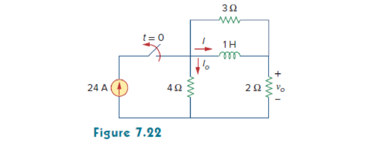
Determine i, io, and vo for all t in the circuit shown in Fig. 7.22. Assume that the switch was closed for a long time. It should be noted that opening a switch in series with an ideal current source creates an infinite voltage at the current source terminals. Clearly this is impossible. For the purposes of problem solving, we can place a shunt resistor in parallel with the source (which now makes it a voltage source in series with a resistor). In more practical circuits, devices that act likecurrent sources are, for the most part, electronic circuits. These circuits will allow the source to act like an ideal current source over its operating range but voltage-limit it when the load resistor becomes too large (as in an open circuit).
Want to see the full answer?
Check out a sample textbook solution
Chapter 7 Solutions
Fundamentals of Electric Circuits


- 2. Design the voltage regulator circuit of Fig. 7-11 to maintain VL at 12 V across RL with Vi that will vary between 16 and 20 V. That is, determine the proper value of Rs and the power rating of the zener diode (Pz). R5 VB V R2402 Fig. (7-11)arrow_forwardFor the circuit shown in Fig.7. what will be the value of RL to get maximum power? Also,find this power.arrow_forwardA moving-coil instrument gives full-scale deflection with 25 mA. The resistance of the coil is 5 ohm. It is required to convert this meter into an ammeter to read up to 5 A. Find (a) the resistance of the shunt to be connected in parallel with the meter, and (b) the value of series resistance for the above meter to read up to a voltage of 20 V.arrow_forward
- Your team is building a robot that is powered with a 35Ah battery. During testing, the robot will run for a maximum of 5 hours before running out of battery, interrupting testing. The team would like to have a better idea of when the robot is going to run out of battery and needs to be recharged. An electrical engineer on your team designs a board to help solve this, with an LTC2944 and a 0.3mohm sense resistor. You are tasked with writing the software to read the accumulated battery discharge, in mAh, at the highest resolution possible. What should register bits B[5:3] be set to, in hexadecimal (please omit ‘0x’ from your answer)? Look up the datasheet to answer this question.arrow_forwardLED flashlights use "white" LEDs which have a diode voltage drop of 4.0V. A LED flashlight has the circuit illustrated and will run off several AAA batteries that have a 1.5 VDC rating. a. What is the minimum number of AAA cells needed to turn on the flashlight. b. Would you arrange the batteries in parallel or in series? Vdd R + LED V fritzingarrow_forward2. Design the voltage regulator circuit of Fig. 7-11 to maintain V, at 12 V across R with V, that will vary between 16 and 20 V. That is, determine the proper value of Rs and the power rating of the zener diode (Pz). R$ V RŽ2402 Fig. 7-11arrow_forward
- Prob 3) Design and construct a circuit having three lamps ( A, B, and C) and one switch. With the switch in the UP position, only lamp A lights and lights at normal brightness. With the switch in the DOWN position, lamp A goes off, but lamps B and C light, and light at half of normal brightness.. .no resistors are allowed in your design.arrow_forwardFET BIASING 33. For the network of Fig. 7.102, determine: a. Ip, and VGso' b. Vps- c. Vp. C9 9-16 V 2 k2 1 M2 VGs (Th) = -3 V Ip (on) = 4 mA VGs (on) = -7 V Vase FIG. 7.102arrow_forwardIn the circuit below a thermistor (R=23.334 k2 at 7 °C) is in a voltage divider circuit with a 13 k2 resistor and supplied from an 8 V supply; the output of the voltage divider is 5.14 V at 7 °C. The loading is represented by connecting a resistor to the voltage divider by closing the switch. Once the load is applied; the output of the voltage divider is 387 mV at 7 °C. (Make sure you understand why from 5.14V to 387mV). the sensor output changes Simulated load subcircuit Sensor subcircuit R4 130 Sw2 output 5.14V VI R2 6800 AThemistor Simulated load subcircuit Sensor subcircuit R4 13k0 Sw2 output 306.94mV V1 R2 6800 AThemistor As the load changes the output will change: 1. with a 91ohm load the output would change to 2. with a 11kohm load the output would change to mV V • The larger resistance has a 9 impact on the sensor load. output, and is therefore the • The lower resistance has a impact on the sensor load. output, and is therefore thearrow_forward
- 1. For the network in Fig. 7.70: a. Does Is = I5 = I6? Explain. b. If Is = 10 A and I1 = 4 A, find I2. c. Does I1 + I2 = I3 + I4? Explain. d. If V2 = 8 V and E = 14 V, find V3. e. If R1 = 4 Ω, R2 = 2 Ω, R3 = 4 Ω, and R4 = 6 Ω, what is RT? f. If all the resistors of the configuration are 20 Ω, what is the source current if the applied voltage is 20 V? g. Using the values of part (f), find the power delivered by the battery and the power absorbed by the total resistance RT.arrow_forwardThe circuit below involves a 90 V battery, three resistors (100, 150, and 200), and three capacitors (0.015F, 0.03F, and 0.03F). The switch stays on position "a" for a long time to reach a stable state. At t = 0 the switch is quickly toggled to position "b". How long after the switch is moved to position"b" will the current through the 2002 is equal to 0.9A. 15Ω 90 V + 0.015F S 10Ω 0.03F 0.03F w 20.00arrow_forwardFor a current source to be neglected, the terminals across the source should be. Select one: a. open circuited O b. replaced by some resistance O c. short circuited O d. replaced by inductorarrow_forward
 Introductory Circuit Analysis (13th Edition)Electrical EngineeringISBN:9780133923605Author:Robert L. BoylestadPublisher:PEARSON
 Delmar's Standard Textbook Of ElectricityElectrical EngineeringISBN:9781337900348Author:Stephen L. HermanPublisher:Cengage Learning
 Programmable Logic ControllersElectrical EngineeringISBN:9780073373843Author:Frank D. PetruzellaPublisher:McGraw-Hill Education
 Fundamentals of Electric CircuitsElectrical EngineeringISBN:9780078028229Author:Charles K Alexander, Matthew SadikuPublisher:McGraw-Hill Education
 Electric Circuits. (11th Edition)Electrical EngineeringISBN:9780134746968Author:James W. Nilsson, Susan RiedelPublisher:PEARSON
 Engineering ElectromagneticsElectrical EngineeringISBN:9780078028151Author:Hayt, William H. (william Hart), Jr, BUCK, John A.Publisher:Mcgraw-hill Education,