
Mechanics of Materials
11th Edition
ISBN: 9780137605460
Author: Russell C. Hibbeler
Publisher: Pearson Education (US)
expand_more
expand_more
format_list_bulleted
Videos
Textbook Question
Chapter 6.5, Problem 106P
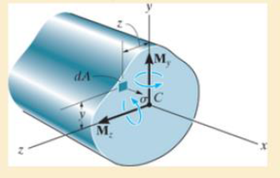
Consider the general case of a prismatic beam subjected to bending-moment components My and Mz when the x, y, z axes pass through the centroid of the cross section. If the material is linear elastic, the normal stress in the beam is a linear function of position such that σ = a + by + cz. Using the equilibrium conditions 0 = ∫A σ dA, My = ∫A zσ dA, Mx = ∫A –yσdA, determine the constants a, b, and c, and show that the normal stress can be determined from the equation σ= [– (MzIy + MyIyz)y + (MyIz + MzIyz)z] /(IyIz – Iyz2), where the moments and products of inertia are defined in Appendix A.
Expert Solution & Answer

Trending nowThis is a popular solution!

Students have asked these similar questions
The beam ABis attached to the wall in the zz plane by a fixed support at A. A force of
F = (- 156i + 58.0j + 350k) N is applied to the end of the beam at B. The weight of the beam can
be modeled with a uniform distributed load of intensity w = 65.0 N/m acting in the negative z direction
along its entire length. Find the support reactions at Á.
F
B
y
а
Values for dimensions on the figure are given in the following table. Note the figure may not be to scale.
Variable Value
5.80 m
5.00 m
3.80 m
A =
i+
j-
k) N
MA =
k) N-m
A moment about the z-axis of 192 N-m is applied to a beam with dimensions b = 85 mm and h = 302 mm. If there are no other loads applied to the beam (My, P, Vy and Vz = 0), what is the normal stress at point F? Give your answer in
kPa to two decimal places with negative indicating compression and positive indicating tension.
b/4
М,
h
E
Ihis
F
h/3
В
M.
D
b/4
5. A 4-point bending test is performed on a beam of length L = 1 m. A load of P = 2000 N is applied
across two loading points a distance a = 0.4 m from the sides of the beam. If the beam has a radius of
r = 1 cm and a yield strength of σ = 250 MPa, does the bar yield? If it's an elastic-perfectly plastic
material, does it fail all the way through the thickness of the bar? What would the yield strength of the
material need to be if we wanted a factor of safety of 1.5?
Chapter 6 Solutions
Mechanics of Materials
Ch. 6.2 - and then draw the shear and moment diagrams for...Ch. 6.2 - In each case, express the shear and moment...Ch. 6.2 - In each case, express the shear and moment...Ch. 6.2 - In each case, express the shear and moment...Ch. 6.2 - In each case, draw the shear and moment diagrams...Ch. 6.2 - In each case, draw the shear and moment diagrams...Ch. 6.2 - In each case, draw the shear and moment diagrams...Ch. 6.2 - In each case, draw the shear and moment diagrams...Ch. 6.2 - Prob. 1PCh. 6.2 - Prob. 2P
Ch. 6.2 - Prob. 3PCh. 6.2 - Express the shear and moment in terms of x for 0 ...Ch. 6.2 - Express the internal shear and moment in the...Ch. 6.2 - Draw the shear and moment diagrams for the shaft....Ch. 6.2 - Determine the shear and moment as functions of x,...Ch. 6.2 - Determine the shear and moment as functions of x,...Ch. 6.2 - Determine the shear and moment as functions of x,...Ch. 6.2 - Determine the shear and moment in the double...Ch. 6.2 - Draw the shear and moment diagrams for the...Ch. 6.2 - Draw the shear and moment diagrams for the shaft....Ch. 6.2 - Draw the shear and moment diagrams for the...Ch. 6.2 - Draw the shear and moment diagrams for the...Ch. 6.2 - Draw the shear and moment diagrams for the...Ch. 6.2 - Prob. 16PCh. 6.2 - Draw the shear and moment diagrams for the simply...Ch. 6.2 - Prob. 19PCh. 6.2 - Draw the shear and moment diagrams for the beam.Ch. 6.2 - Draw the shear and moment diagrams for the...Ch. 6.2 - The 150-lb man sits in the center of the boat,...Ch. 6.2 - Prob. 24PCh. 6.2 - Draw the shear and moment diagrams for the beam.Ch. 6.2 - Prob. 26PCh. 6.2 - Draw the shear and moment diagrams for the beam....Ch. 6.2 - Prob. 29PCh. 6.2 - Prob. 30PCh. 6.2 - Prob. 31PCh. 6.2 - Prob. 34PCh. 6.2 - Prob. 35PCh. 6.2 - The beam is used to support a uniform load along...Ch. 6.2 - Prob. 39PCh. 6.2 - Prob. 42PCh. 6.2 - Prob. 43PCh. 6.2 - Prob. 44PCh. 6.2 - Prob. 45PCh. 6.2 - The truck is to be used to transport the concrete...Ch. 6.4 - If the beam is subjected to a bending moment of M...Ch. 6.4 - If the beam is subjected to a bending moment of M...Ch. 6.4 - If the beam is subjected to a bending moment of M...Ch. 6.4 - If the beam is subjected to a bending moment of M...Ch. 6.4 - If the beam is subjected to a bending moment of M...Ch. 6.4 - Determine the moment M that will produce a maximum...Ch. 6.4 - Determine the maximum tensile and compressive...Ch. 6.4 - The beam is constructed from four pieces of wood,...Ch. 6.4 - The beam is constructed from four pieces of wood,...Ch. 6.4 - The beam is made from three boards nailed together...Ch. 6.4 - The beam is made from three boards nailed together...Ch. 6.4 - Prob. 54PCh. 6.4 - The tubular shaft is supported by a smooth thrust...Ch. 6.4 - Prob. 57PCh. 6.4 - If the beam is subjected to an internal moment or...Ch. 6.4 - If the beam is made of material having an...Ch. 6.4 - Prob. 60PCh. 6.4 - Prob. 61PCh. 6.4 - The beam is subjected to a moment of M = 40 kN m....Ch. 6.4 - The steel shaft has a diameter of 2 in. It is...Ch. 6.4 - Determine the dimension a of a beam having a...Ch. 6.4 - A shaft is made of a polymer having an elliptical...Ch. 6.4 - Solve Prob. 6-65 if the moment M = 50 N m is...Ch. 6.4 - Prob. 67PCh. 6.4 - If M=4kipft , determine the resultant force the...Ch. 6.4 - The strut on the utility pole supports the cable...Ch. 6.4 - The pin is used to connect the three links...Ch. 6.4 - Prob. 75PCh. 6.4 - A timber beam has a cross section which is...Ch. 6.4 - If the beam is subjected to an internal moment of...Ch. 6.4 - If the allowable tensile and compressive stress...Ch. 6.4 - If the beam is subjected to an internal moment of...Ch. 6.4 - Prob. 80PCh. 6.4 - Prob. 81PCh. 6.4 - Prob. 82PCh. 6.4 - Prob. 83PCh. 6.4 - If the intensity of the load w=15kN/m , determine...Ch. 6.4 - Prob. 85PCh. 6.4 - Determine the absolute maximum bending stress in...Ch. 6.4 - Prob. 87PCh. 6.4 - Prob. 88PCh. 6.4 - If the compound beam in Prob. 642 has a square...Ch. 6.4 - If the beam in Prob. 628 has a rectangular cross...Ch. 6.4 - Determine the absolute maximum bending stress in...Ch. 6.4 - Determine, to the nearest millimeter, the smallest...Ch. 6.4 - If the beam in Prob.63 has a rectangular cross...Ch. 6.4 - The simply supported truss is subjected to the...Ch. 6.4 - If d = 450 mm, determine the absolute maximum...Ch. 6.4 - If the allowable bending stress is allow = 6 MPa,...Ch. 6.4 - Prob. 102PCh. 6.4 - Prob. 103PCh. 6.5 - Determine the bending stress at corners A and B....Ch. 6.5 - Determine the maximum bending stress in the beams...Ch. 6.5 - The member has a square cross section and is...Ch. 6.5 - The member has a square cross section and is...Ch. 6.5 - Consider the general case of a prismatic beam...Ch. 6.5 - The steel shaft is subjected to the two loads. If...Ch. 6.5 - The 65-mm-diameter steel shaft is subjected to the...Ch. 6.5 - For the section, lz = 31.7(10-5) m4, lY =...Ch. 6.5 - For the section, lz, = 31.7(10-5) m4, lY =...Ch. 6.9 - The composite beam is made of steel (A) bonded to...Ch. 6.9 - The composite beam is made of steel (A) bonded to...Ch. 6.9 - Segment A of the composite beam is made from...Ch. 6.9 - Segment A of the composite beam is made from...Ch. 6.9 - A wood beam is reinforced with steel straps at its...Ch. 6.9 - The composite beam is made of A-36 steel (A)...Ch. 6.9 - The composite beam is made of A-36 steel (A)...Ch. 6.9 - If the beam is subjected to a moment of M = 45 kN...Ch. 6.9 - The Douglas Fir beam is reinforced with A-36 steel...Ch. 6.9 - For the curved beam in Fig. 640a, show that when...Ch. 6.9 - The curved member is subjected to the moment of M...Ch. 6.9 - The curved member is made from material having an...Ch. 6.9 - If P = 3 kN, determine the bending stress at...Ch. 6.9 - If the maximum bending stress at section a-a is...Ch. 6.9 - The elbow of the pipe has an outer radius of 0.75...Ch. 6.9 - The curved bar used on a machine has a rectangular...Ch. 6.9 - The steel rod has a circular cross section. If it...Ch. 6.9 - Prob. 150PCh. 6.9 - Prob. 151PCh. 6.9 - The bar has a thickness of 1 in. and the allowable...Ch. 6.9 - The bar has a thickness of 1 in. and is subjected...Ch. 6.9 - Prob. 154PCh. 6.9 - The bar is subjected to a moment of M=17.5Nm If...Ch. 6.9 - Prob. 156PCh. 6.9 - Prob. 157PCh. 6.10 - The beam is made of an elastic plastic material...Ch. 6.10 - The wide-flange member is made from an elastic...Ch. 6.10 - The rod has a circular cross section. If it is...Ch. 6.10 - The rod has a circular cross section. If it is...Ch. 6.10 - The beam is made of an elastic perfectly plastic...Ch. 6.10 - Determine the plastic moment Mp that can be...Ch. 6.10 - Prob. 164PCh. 6.10 - Prob. 166PCh. 6.10 - Prob. 170PCh. 6.10 - Prob. 171PCh. 6.10 - The box beam is made of an elastic perfectly...Ch. 6.10 - The plexiglass bar has a stress-strain curve that...Ch. 6 - Determine the shape factor for the wide-flange...Ch. 6 - The compound beam consists of two segments that...Ch. 6 - The composite beam consists of a wood core and two...Ch. 6 - If it resists a moment of M = 125 N m, determine...Ch. 6 - Determine the maximum bending stress in the handle...Ch. 6 - The curved beam is subjected to a bending moment...Ch. 6 - Determine the shear and moment in the beam as...Ch. 6 - A wooden beam has a square cross section as shown...Ch. 6 - Draw the shear and moment diagrams for the shaft...Ch. 6 - The strut has a square cross section a by a and is...
Knowledge Booster


Learn more about
Need a deep-dive on the concept behind this application? Look no further. Learn more about this topic, mechanical-engineering and related others by exploring similar questions and additional content below.Similar questions
- Determine the x, y, z components of internal loading at a section passing through point B in the pipe assembly. F, = {200i – 100j – 400k } N F2 = {300i – 500k} N. - - Neglect the weight of the pipe. A F2 В 1 m y 1 m 1.5 m F1 What is the bending moment x component at B?arrow_forwardMechanic of Materials In the system shown the ABC bar is subjected to a charge Fz = P (in kN) at the same time as a moment My = 3P (kN*m). Using the Mohr Circle determine (in terms of P and in units kN and m). The stress state of the point a' in the xy plane. The stress state for an angle of 30° clockwise seen from z. Data: L= 3.0 m Φ = 25 cm.arrow_forwardUse the method of section to find the force in members BD, BE and CE.arrow_forwardDetermine the resultant internal loadings acting on the cross section at B for the piping system fixed at the point A with a mass of 12 kg/m. Neglect the weight of the wrench CD. 200 mm 400 mm 300 mm B 1000 N 60 NA 150 mm A 60 N 150 mm D Include in your answer: Free body diagram (FDB) Static equilibrium equationsarrow_forwardA stress element in a rock mass making up a slope experiences a 2D stress as follows: σx = 8 MPa, σy = 4 MPa , tauxy = 3 MPa a. Draw the Mohr circle. On Mohr's circle, mark the location of the x and y planes, mark the angle of rotation θ from the x plane to the σ₁,σ3,and taumax plane. Prove that the angle of rotation of the Mohr circle is 2 times the angle of rotation of the element. b. Write down the coordinates of the center of Mohr's circle and calculate its radius.arrow_forwardAs the electric motor rotates at a constant speed, it applies a torque of 500 Nm to the ABCD shaft. Determine the torsion angle between B and C since G = 27 GPa and the torques shown in the figure are applied to the pulleys B and C.arrow_forwardDetermine the moment reaction at point A in the clockwise direction in N.m? Set P =411 N, Y =197 mm, & X= 420 mm. Note: the figure is not to scale and your answer should contain only numbers, not units. 60 30arrow_forwardConsider the joint steel bars below. If 50,000 lb force is applied at point A, determine the displacement of point A along x and y axis, and the normal reactions in the supports. Assume EST = 29 x 10° psi. Area of steel bar is 2.5 in². 50 000 16 50 15 in A 10 in 10 in 15 inarrow_forwardDraw the shear force and bending moment diagram for the loaded beam shown below. Also mark the salient points in the diagram. where F=20 N, F2=70N, F3=80N, a=3m, b=2 m, c=6m & d=2m. Neglect the self weight of the beam. F1 F2 F3 b Shear force at the point "B" = N) (unit in The Reaction at the support "A" RA (Unit in N) is The Reaction at the support "B" Rg (Unit in N) is Bending Moment with respect to "B" = (unit Nm) Shear force at the point "A" = N) Bending Moment with respect to "E" = (unit Nm) (unit in Shear force at the point "C" = _ (unit in N) Bending Moment with respect to "D" = (unit Nm) Bending Moment with respect to "C" = (unit Nm) Shear force at the point "D" = N) (unit in Bending Moment with respect to "A" = (unit Nm) Shear force at the point "E" = N) (unit inarrow_forwardThe force P is applied to the bar, which is made from an elastic perfectly plastic material. Construct a graph to show how the force in each section AB and BC (vertical axis) varies as P (horizontal axis) is increased. The bar has cross-sectional areas of 1 in2 in region AB and 4 in2 in region BC. Take sY = 30 ksi.arrow_forward4. The rigid lever arm is supported by two A-36 steel wires having the same diameter of 4 mm. If a force of P = 3 kN is applied to the handle, determine the force developed in both wires and their corresponding elongations. Consider A-36 steel as an elastic-perfectly plastic material. 450 mm 150 mm 150 mm 30 300 mm B.arrow_forwardFigure 0.8 m 450 N 300 N-m 0.4 m. 45 B < 1 of 1 0.4 m 0,6 m ▼ Part A Determine the components of reaction acting at the smooth journal bearing A. (Figure 1) Enter the x, y, and z components of the force separated by commas. ΓΨΓ ΑΣΦ ↓↑ vec 4 Az. Ay, A₂= Submit Part B Request Answer Determine the components of reaction acting at the smooth journal bearing B. Enter the x, y, and z components of the force separated by commas. IVE ΑΣΦ ↓t vec B₂, B₂, B₂ = Submit Request Answer N Narrow_forwardarrow_back_iosSEE MORE QUESTIONSarrow_forward_ios
Recommended textbooks for you
 Elements Of ElectromagneticsMechanical EngineeringISBN:9780190698614Author:Sadiku, Matthew N. O.Publisher:Oxford University Press
 Mechanics of Materials (10th Edition)Mechanical EngineeringISBN:9780134319650Author:Russell C. HibbelerPublisher:PEARSON
 Thermodynamics: An Engineering ApproachMechanical EngineeringISBN:9781259822674Author:Yunus A. Cengel Dr., Michael A. BolesPublisher:McGraw-Hill Education
 Control Systems EngineeringMechanical EngineeringISBN:9781118170519Author:Norman S. NisePublisher:WILEY
 Mechanics of Materials (MindTap Course List)Mechanical EngineeringISBN:9781337093347Author:Barry J. Goodno, James M. GerePublisher:Cengage Learning
 Engineering Mechanics: StaticsMechanical EngineeringISBN:9781118807330Author:James L. Meriam, L. G. Kraige, J. N. BoltonPublisher:WILEY
Elements Of Electromagnetics
Mechanical Engineering
ISBN:9780190698614
Author:Sadiku, Matthew N. O.
Publisher:Oxford University Press
Mechanics of Materials (10th Edition)
Mechanical Engineering
ISBN:9780134319650
Author:Russell C. Hibbeler
Publisher:PEARSON
Thermodynamics: An Engineering Approach
Mechanical Engineering
ISBN:9781259822674
Author:Yunus A. Cengel Dr., Michael A. Boles
Publisher:McGraw-Hill Education
Control Systems Engineering
Mechanical Engineering
ISBN:9781118170519
Author:Norman S. Nise
Publisher:WILEY
Mechanics of Materials (MindTap Course List)
Mechanical Engineering
ISBN:9781337093347
Author:Barry J. Goodno, James M. Gere
Publisher:Cengage Learning
Engineering Mechanics: Statics
Mechanical Engineering
ISBN:9781118807330
Author:James L. Meriam, L. G. Kraige, J. N. Bolton
Publisher:WILEY
Extent of Reaction; Author: LearnChemE;https://www.youtube.com/watch?v=__stMf3OLP4;License: Standard Youtube License