
Mechanics of Materials
9th Edition
ISBN: 9780133254426
Author: Russell C. Hibbeler
Publisher: Prentice Hall
expand_more
expand_more
format_list_bulleted
Videos
Textbook Question
Chapter 5.5, Problem 5.88P
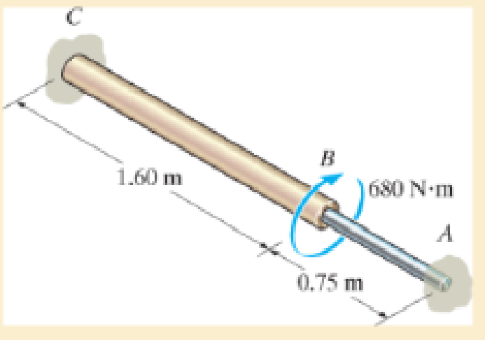
It is fixed at its ends and subjected to a torque of T = 680 N · m. If the steel portion has a diameter of 30 mm, determine the required diameter of the brass portion so the reactions at the walls will be the same. Gst = 75 GPa, Gbr = 39 GPa.
Expert Solution & Answer
Want to see the full answer?
Check out a sample textbook solution
Students have asked these similar questions
A rod is made from two segments: AB is steel and BC is brass. It is fixed at its ends and subjected to a torque of T=680 N⋅m. The steel portion has a diameter of 25 mm
Determine the required diameter of the brass portion so the reactions at the walls will be the same. Take Gst = 75 GPa, Gbr = 39 GPa.
The solid-circular member AC, having a diameter D and a shear modulus of 69 GPa, is subjected to the torques 2T and 3T at points A and B, respectively. If tallow = 35 MPa and (fA/C)allow =2o, determine the maximum permissible value of the torque T.
Use the table given below and your student ID to find the values of L1, L2, and D.
Student ID
L1 (m)
L2 (m)
D (mm)
1131731
1
0.6
78
The assembly below consists of a steel rod CB and an aluminium rod BA, each having a diameter of 12 mm.
If the rod is subjected to the axial loadings at A and at the coupling B, determine the displacement of the coupling B and the end A.
The unstretched length of each segment is shown below. Neglect the size of the connections at B and C, and assume that they are rigid. Est = 200 GPa, Eal = 70 GPa.
Chapter 5 Solutions
Mechanics of Materials
Ch. 5.3 - Determine the internal torque at each section and...Ch. 5.3 - Determine the. internal torque at each section and...Ch. 5.3 - The solid and hollow shafts are each subjected to...Ch. 5.3 - The motor delivers 10 hp to the shaft. If it...Ch. 5.3 - The solid circular shaft is subjected to an...Ch. 5.3 - The hollow circular shaft is subjected to an...Ch. 5.3 - The shaft is hollow from A to B and solid from B...Ch. 5.3 - Determine the maximum shear stress in the...Ch. 5.3 - Determine the maximum shear stress in the shaft at...Ch. 5.3 - Determine the shear stress a: point A on the...
Ch. 5.3 - The solid 50-mm-diameter shaft is subjected to the...Ch. 5.3 - The gear motor can develop 3 hp when it turns at...Ch. 5.3 - The solid shaft of radius r is subjected to a...Ch. 5.3 - The solid shaft of radius r is subjected to a...Ch. 5.3 - 5-3. The solid shaft is fixed to the support at C...Ch. 5.3 - The copper pipe has an outer diameter of 40 mm and...Ch. 5.3 - The copper pipe has an outer diameter of 2.50 in....Ch. 5.3 - Prob. 5.6PCh. 5.3 - Prob. 5.7PCh. 5.3 - The solid 30-mm-diameter shaft is used to transmit...Ch. 5.3 - The solid shaft is fixed to the support at C and...Ch. 5.3 - Prob. 5.10PCh. 5.3 - The assembly consists of two sections of...Ch. 5.3 - Prob. 5.12PCh. 5.3 - 5-13. If The tubular shaft is made from material...Ch. 5.3 - A steel tube having an outer diameter of 2.5 in....Ch. 5.3 - Prob. 5.15PCh. 5.3 - Prob. 5.16PCh. 5.3 - The rod has a diameter of 1 in. and a weight of 10...Ch. 5.3 - The rod has a diameter of 1 in. and a weight of 15...Ch. 5.3 - 5-19. The shaft consists of solid 80-mm-diameter...Ch. 5.3 - Prob. 5.20PCh. 5.3 - 5-21. If the 40-mm-diameter rod is subjected to a...Ch. 5.3 - Prob. 5.22PCh. 5.3 - Prob. 5.23PCh. 5.3 - Prob. 5.24PCh. 5.3 - Prob. 5.25PCh. 5.3 - Prob. 5.26PCh. 5.3 - Prob. 5.27PCh. 5.3 - Prob. 5.28PCh. 5.3 - Prob. 5.29PCh. 5.3 - Prob. 5.30PCh. 5.3 - The solid steel shaft AC has a diameter of 25 mm...Ch. 5.3 - The pump operates using the motor that has a power...Ch. 5.3 - Prob. 5.33PCh. 5.3 - Prob. 5.34PCh. 5.3 - Prob. 5.35PCh. 5.3 - Prob. 5.36PCh. 5.3 - Prob. 5.37PCh. 5.3 - Prob. 5.38PCh. 5.3 - Prob. 5.39PCh. 5.3 - Prob. 5.40PCh. 5.3 - The A-36 steel tubular shaft is 2 m long and has...Ch. 5.3 - Prob. 5.42PCh. 5.3 - The solid shaft has a linear taper from rA at one...Ch. 5.3 - *5-44. The rod has a diameter of 0.5 in. and...Ch. 5.3 - 5-45. Solve Prob. 5-44 for the maximum torsional...Ch. 5.3 - A motor delivers 500 hp to the shaft, which is...Ch. 5.4 - The 60 mm-diameter steel shaft is subjected to the...Ch. 5.4 - Prob. 5.10FPCh. 5.4 - The hollow 6061-T6 aluminum shaft has an outer and...Ch. 5.4 - A series of gears are mounted on the...Ch. 5.4 - The 80-mm-diameter shaft is made of steel. If it...Ch. 5.4 - The 80-mm-diameter shaft is made of steel. If it...Ch. 5.4 - The propellers of a ship are connected to an A-36...Ch. 5.4 - Show that the maximum shear strain in the shaft is...Ch. 5.4 - 5-49. The A-36 steel axle is made from tubes AB...Ch. 5.4 - Prob. 5.50PCh. 5.4 - Determine the maximum allowable torque T. Also,...Ch. 5.4 - If the allowable shear stress is allow = 80 MPa,...Ch. 5.4 - Prob. 5.53PCh. 5.4 - If gear B supplies 15 kW of power, while gears A,...Ch. 5.4 - If the shaft is made of steel with the allowable...Ch. 5.4 - *5-56. The A-36 steel axle is made from tubes AB...Ch. 5.4 - If the rotation of the 100-mm-diameter A-36 steel...Ch. 5.4 - If the rotation of the 100-mm-diameter A-36 steel...Ch. 5.4 - It has a diameter of 1 in. and is supported by...Ch. 5.4 - Prob. 5.60PCh. 5.4 - Prob. 5.61PCh. 5.4 - Prob. 5.62PCh. 5.4 - Prob. 5.63PCh. 5.4 - Prob. 5.64PCh. 5.4 - Prob. 5.65PCh. 5.4 - When it is rotating at 80 rad/s. it transmits 32...Ch. 5.4 - It is required to transmit 35 kW of power from the...Ch. 5.4 - Prob. 5.68PCh. 5.4 - If a torque of T = 50 N m is applied to the bolt...Ch. 5.4 - If a torque of T= 50N m is applied to the bolt...Ch. 5.4 - Prob. 5.72PCh. 5.4 - If the shaft is subjected to a torque T at its...Ch. 5.4 - Prob. 5.74PCh. 5.4 - Prob. 5.75PCh. 5.4 - *5-76. A cylindrical spring consists of a rubber...Ch. 5.5 - Gst = 75 GPa.Ch. 5.5 - The A992 steel shaft has a diameter of 60 mm and...Ch. 5.5 - If the shaft is fixed at its ends A and B and...Ch. 5.5 - Prob. 5.80PCh. 5.5 - Prob. 5.81PCh. 5.5 - 5-82. The shaft is made from a solid steel section...Ch. 5.5 - 5-83. The motor A develops a torque at gear B of...Ch. 5.5 - If the allowable shear stresses for the magnesium...Ch. 5.5 - If a torque of T = 5 kNm is applied to end A,...Ch. 5.5 - Each has a diameter of 25 mm and they are...Ch. 5.5 - Each has a diameter of 25 mm and they are...Ch. 5.5 - It is fixed at its ends and subjected to a torque...Ch. 5.5 - 5–89. Determine the absolute maximum shear stress...Ch. 5.5 - The shaft is subjected to a torque of 800 lbft....Ch. 5.5 - Prob. 5.91PCh. 5.5 - The shaft is made of 2014-T6 aluminum alloy and is...Ch. 5.5 - The tapered shaft is confined by the fixed...Ch. 5.5 - Determine the reactions at the fixed supports A...Ch. 5.7 - 5-95. The aluminum rod has a square cross section...Ch. 5.7 - Prob. 5.96PCh. 5.7 - Prob. 5.97PCh. 5.7 - If it is subjected to the torsional loading,...Ch. 5.7 - Solve Prob.5-98 for the maximum shear stress...Ch. 5.7 - determine the maximum shear stress in the shaft....Ch. 5.7 - If the shaft has an equilateral triangle cross...Ch. 5.7 - 5-102. The aluminum strut is fixed between the two...Ch. 5.7 - is applied to the tube If the wall thickness is...Ch. 5.7 - If it is 2 m long, determine the maximum shear...Ch. 5.7 - Also, find the angle of twist of end B. The shaft...Ch. 5.7 - Also, find the corresponding angle of twist at end...Ch. 5.7 - If the solid shaft is made from red brass C83400...Ch. 5.7 - If the solid shaft is made from red brass C83400...Ch. 5.7 - The tube is 0.1 in. thick.Ch. 5.7 - 5-110. For a given maximum average shear stress,...Ch. 5.7 - 5-111. A torque T is applied to two tubes having...Ch. 5.7 - By what percentage is the torsional strength...Ch. 5.7 - 5-113. Determine the constant thickness of the...Ch. 5.7 - 5-114. Determine the torque T that can be applied...Ch. 5.7 - If the allowable shear stress is allow = 8 ksi,...Ch. 5.7 - *5-116. The tube is made of plastic, is 5 mm...Ch. 5.7 - 5–117. The mean dimensions of the cross section of...Ch. 5.7 - 5–118. The mean dimensions of the cross section of...Ch. 5.7 - If it is subjected to a torque of T = 40 Nm....Ch. 5.10 - If the transition between the cross sections has a...Ch. 5.10 - 5–121. The step shaft is to be designed to rotate...Ch. 5.10 - Prob. 5.122PCh. 5.10 - 5–123. The transition at the cross sections of the...Ch. 5.10 - *5–124. The steel used for the step shaft has an...Ch. 5.10 - 5–125. The step shaft is subjected to a torque of...Ch. 5.10 - Determine the radius of the elastic core produced...Ch. 5.10 - Assume that the material becomes fully plastic.Ch. 5.10 - diameter is subjected to a torque of 100 in.kip....Ch. 5.10 - Determine the torque T needed to form an elastic...Ch. 5.10 - Determine the torque applied to the shaft.Ch. 5.10 - 5–131. An 80-mm-diameter solid circular shaft is...Ch. 5.10 - Determine the ratio of the plastic torque Tp to...Ch. 5.10 - 5–133. If the step shaft is elastic-plastic as...Ch. 5.10 - 5–134. The solid shaft is made from an...Ch. 5.10 - 5–135. A 1.5-in.-diameter shaft is made from an...Ch. 5.10 - *5–136. The tubular shaft is made of a...Ch. 5.10 - 5–137. The shaft is made from a strain-hardening...Ch. 5.10 - 5–138. The tube is made of elastic-perfectly...Ch. 5.10 - Determine the torque required to cause a maximum...Ch. 5.10 - *5–140. The 2-m-long tube is made of an...Ch. 5.10 - is made from an elastic perfectly plastic material...Ch. 5.10 - 5–142. The 2-m-long lube is made from an...Ch. 5 - The shaft is made of A992 steel and has an...Ch. 5 - The shaft is made of A992 steel and has an...Ch. 5 - Determine the shear stress at the mean radius p =...Ch. 5 - If the thickness of its 2014-T6-aluminum skin is...Ch. 5 - Determine which shaft geometry will resist the...Ch. 5 - If couple forces P = 3 kip are applied to the...Ch. 5 - If the allowable shear stress for the aluminum is...Ch. 5 - Determine the angle of twist of its end A if it is...Ch. 5 - This motion is caused by the unequal belt tensions...
Knowledge Booster


Learn more about
Need a deep-dive on the concept behind this application? Look no further. Learn more about this topic, mechanical-engineering and related others by exploring similar questions and additional content below.Similar questions
- Four pulleys are attached to the 50-mm-diameter aluminum shaft. If torques are applied to the pulleys as shown in the figure, determine the angle of rotation of pulley D relative to pulley A. Use G = 28 GPa for aluminum. 600 N m 900 N m 1100 N m 800 N m 2 m 2 m 3 marrow_forwardFour pulleys are attached to the 50-mm-diameter aluminum shaft. If torques are applied to the pulleys as shown in the figure, determine the angle of rotation of pulley D relative to pulley A. Use G = 28 GPa for aluminum.arrow_forward3. If P = 150 kN, determine the decrease in the diameter of rod BC. Rod BC is made of A-36 steel of E = 200GPa and has a diameter of 40 mm. Use v = 0.42. P -1 m- -1 m P -1m- B 0.75 m 1 marrow_forward
- Problem 2. The assembly consists of three titanium (Ti- 6A1-4V) rods and a rigid bar AC. The cross-sectional area of each rod is given in the figure. If a force of 6 kip is applied to the ring F, determine the horizontal displacement of point F, and determine the angle of tilt of rigid bar AC. B D 4 ft ACD = 1 in² AAB 6 ft 1.5 in² E 2 ft 1 ft 1 ft AEF = 2 in² 6 kiparrow_forwardThe brass wire has a triangular cross section, 2 mm on a side. If the yield stress for brass is tY = 205 MPa, determine the maximum torque T to which it can be subjected so that the wire will not yield. If this torque is applied to the 4-m-long segment, determine the greatest angle of twist of one end of the wire relative to the other end that will not cause permanent damage to the wire. Gbr = 37 GPa.arrow_forward4-2. The copper shaft is subjected to the axial loads shown. Determine the displacement of end A with respect to end D if the diameters of each segment are dAB = 20 mm, dBc=25 mm, and dcp=12 mm. Take Ecu= 126 GPa. Ans: = 3.46 mm away from end D. + 2 m 3.75 m 2.5 m 22.5 kN 9 kN 36 kN 27 kN A 22.5 kN B C 9 kNarrow_forward
- Can someone please explain the step-by-step process of this. Thank you so much! The d = 12-mm-diameter solid rod passes through a D = 17-mm-diameter hole in the support plate. When a load P is applied to the rod, the rod head rests on the support plate. The support plate has a thickness of b = 13 mm. The rod head has a diameter of a = 24 mm, and the head has a thickness of t = 9 mm. The shear stress in the rod head cannot exceed 130 MPa, the punching shear stress in the support plate cannot exceed 85 MPa, and the bearing stress between the rod head and the support plate cannot exceed 130 MPa. Determine the maximum value of Pmax that can be supported by the structure.arrow_forwardThe 20-mm diameter steel rod BC is attached to the lever AB and to the fixed support C. The uniform steel lever is 10mm thick and 30mm deep. Using the method of work and energy, determine the deflection of point A when L = 600 mm. Use E = 200 GPa and G = 77.2 GPa Now solve the problem again but add a torque at point B, which acts together with P as shown in the figure.arrow_forwardThe assembly consists of three titanium (Ti-6A1- 4V) rods and a rigid bar AC. The cross-section area of each rod is given in the figure. If a force of 60 kip is applied o the ring F, determine the horizontal displacement of point F. Hint: Refer to the textbook appendix for material properties. AEF 2 in² 1 ft = 60 kip F-2 ft- 2 ft A C 6 ft B AAB = 1 in² E ACD = 1.5 in² 6 ft Darrow_forward
- The cylindrical steel column has an outer diameter of 4 in. and inner diameter of 3.5 in. The column is separated from the concrete foundation by a square bearing plate. The working compressive stress is 26 000 psi for the column, and the working bearing stress is 1200 psi for concrete. Find the largest force P that can be applied to the column. Express your answer in Ib. 4 in. 3.5 in. 4/4 7 in.arrow_forwardThe rigid lever arm is supported by two A-36 steel wires having the same diameter of 4 mm. If a force of P = 3 kN is applied to the handle, determine the force developed in both wires and their corresponding elongations. Consider A-36 steel as an elastic perfectly plastic material.arrow_forwardTwo forces, each of magnitude P, are applied to the wrench. The diameter of the steel shaft AB is 30mm. Determine the largest allowable value of P if the shear stress in the shaft is not to exceed 120MPa and it's angle of twist is limited to 7deg. Use G=83GPa for steel. -Draw and label the diagram correctly, No diagram in the solution will be marked wrong. -Shortcut solution will be marked wrong.arrow_forward
arrow_back_ios
SEE MORE QUESTIONS
arrow_forward_ios
Recommended textbooks for you
 Elements Of ElectromagneticsMechanical EngineeringISBN:9780190698614Author:Sadiku, Matthew N. O.Publisher:Oxford University Press
 Mechanics of Materials (10th Edition)Mechanical EngineeringISBN:9780134319650Author:Russell C. HibbelerPublisher:PEARSON
 Thermodynamics: An Engineering ApproachMechanical EngineeringISBN:9781259822674Author:Yunus A. Cengel Dr., Michael A. BolesPublisher:McGraw-Hill Education
 Control Systems EngineeringMechanical EngineeringISBN:9781118170519Author:Norman S. NisePublisher:WILEY
 Mechanics of Materials (MindTap Course List)Mechanical EngineeringISBN:9781337093347Author:Barry J. Goodno, James M. GerePublisher:Cengage Learning
 Engineering Mechanics: StaticsMechanical EngineeringISBN:9781118807330Author:James L. Meriam, L. G. Kraige, J. N. BoltonPublisher:WILEY
Elements Of Electromagnetics
Mechanical Engineering
ISBN:9780190698614
Author:Sadiku, Matthew N. O.
Publisher:Oxford University Press
Mechanics of Materials (10th Edition)
Mechanical Engineering
ISBN:9780134319650
Author:Russell C. Hibbeler
Publisher:PEARSON
Thermodynamics: An Engineering Approach
Mechanical Engineering
ISBN:9781259822674
Author:Yunus A. Cengel Dr., Michael A. Boles
Publisher:McGraw-Hill Education
Control Systems Engineering
Mechanical Engineering
ISBN:9781118170519
Author:Norman S. Nise
Publisher:WILEY
Mechanics of Materials (MindTap Course List)
Mechanical Engineering
ISBN:9781337093347
Author:Barry J. Goodno, James M. Gere
Publisher:Cengage Learning
Engineering Mechanics: Statics
Mechanical Engineering
ISBN:9781118807330
Author:James L. Meriam, L. G. Kraige, J. N. Bolton
Publisher:WILEY
Understanding Failure Theories (Tresca, von Mises etc...); Author: The Efficient Engineer;https://www.youtube.com/watch?v=xkbQnBAOFEg;License: Standard youtube license