
Physics for Scientists and Engineers with Modern Physics
4th Edition
ISBN: 9780131495081
Author: Douglas C. Giancoli
Publisher: Addison-Wesley
expand_more
expand_more
format_list_bulleted
Videos
Textbook Question
Chapter 26, Problem 16P
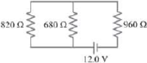
(II) Determine (a) the equivalent resistance of the circuit shown in Fig. 26–39, and (b) the voltage across each resistor.
FIGURE 26–39 Problem 16.
Expert Solution & Answer
Want to see the full answer?
Check out a sample textbook solution
Students have asked these similar questions
(II) For the circuit shown in Fig. 19–55, find the potential
difference between points a
and b. Each resistor has
R
R = 160 N and each bat-
tery is 1.5 V.
a
1.5 V•
R:
R
R
1.5 V
FIGURE 19-55
Problem 27.
b
(I) Calculate the current in the circuit of Fig. 19–53, and
show that the sum of all the
r= 2.0 2
voltage changes around the
circuit is zero.
9.0 V
9.5 Q
FIGURE 19–53
Problem 25.
14.0 2
(II) Determine (a) the equivalent resistance of the circuit
shown in Fig. 19–48, (b) the voltage across each resistor, and
(c) the current through
each resistor.
750 Ω.
680 2
990 Ω
FIGURE 19–48
Problem 16.
12.0 V
Chapter 26 Solutions
Physics for Scientists and Engineers with Modern Physics
Ch. 26.1 - Repeat Example 261 assuming now that the...Ch. 26.2 - You have a 10- and a 15- resistor. What is the...Ch. 26.3 - Write the equation for the lower loop abcdefga of...Ch. 26.4 - If the jumper cables of Example 2610 were...Ch. 26.5 - In 10 times constants, the charge on the capacitor...Ch. 26 - Explain why birds can sit on power lines safely,...Ch. 26 - Discuss the advantages and disadvantages of...Ch. 26 - If all you have is a 120-V line, would it be...Ch. 26 - Two lightbulbs of resistance R1 and R2 (R2 R1)...Ch. 26 - Household outlets are often double outlets. Are...
Ch. 26 - With two identical lightbulbs and two identical...Ch. 26 - If two identical resistors are connected in series...Ch. 26 - You have a single 60-W bulb on in your room. How...Ch. 26 - When applying Kirchhoffs loop rule (such as in...Ch. 26 - Compare and discuss the formulas for resistors and...Ch. 26 - For what use are batteries connected in series?...Ch. 26 - Can the terminal voltage of a battery ever exceed...Ch. 26 - Explain in detail how you could measure the...Ch. 26 - In an RC circuit, current flows from the battery...Ch. 26 - Given the circuit shown in Fig. 2634, use the...Ch. 26 - Figure 2635 is a diagram of a capacitor (or...Ch. 26 - Design a circuit in which two different switches...Ch. 26 - What is the main difference between an analog...Ch. 26 - What would happen if you mistakenly used an...Ch. 26 - Explain why an ideal ammeter would have zero...Ch. 26 - A voltmeter connected across a resistor always...Ch. 26 - A small battery-operated flashlight requires a...Ch. 26 - Different lamps might have batteries connected in...Ch. 26 - Prob. 1PCh. 26 - (I) Four 1.50-V cells are connected in series to a...Ch. 26 - (II) A 1.5-V dry cell can be tested by connecting...Ch. 26 - (II) What is the internal resistance of a 12.0-V...Ch. 26 - (I) A 650- and a 2200- resistor are connected in...Ch. 26 - (I) Three 45- lightbulbs and three 65- lightbulbs...Ch. 26 - (I) Suppose that you have a 680-, a 720-, and a...Ch. 26 - (I) How many 10- resistors must be connected in...Ch. 26 - (II) Suppose that you have a 9.0-V battery and you...Ch. 26 - Three 1.70-k resistors can be connected together...Ch. 26 - (II) A battery with an emf of 12.0 V shows a...Ch. 26 - (II) Eight identical bulbs are connected in series...Ch. 26 - (II) Eight bulbs are connected in parallel to a...Ch. 26 - (II) The performance of the starter circuit in an...Ch. 26 - (II) A close inspection of an electric circuit...Ch. 26 - (II) Determine (a) the equivalent resistance of...Ch. 26 - (II) A 75-W, 110-V bulb is connected in parallel...Ch. 26 - (II) (a) Determine the equivalent resistance of...Ch. 26 - (II) Whal is the net resistance of the circuit...Ch. 26 - (II) Calculate the current through each resistor...Ch. 26 - (II) The two terminals of a voltage source with...Ch. 26 - (II) Two resistors when connected in series to a...Ch. 26 - (III) Three equal resistors (R) are connected to a...Ch. 26 - (III) A 2.8-k and a 3.7-k resistor are connected...Ch. 26 - (III) Consider the network of resistors shown in...Ch. 26 - (III) You are designing a wire resistance heater...Ch. 26 - (I) Calculate the current in the circuit of Fig....Ch. 26 - (II) Determine the terminal voltage of each...Ch. 26 - (II) For the circuit shown in Fig. 2647, find the...Ch. 26 - (II) (a) A network of five equal resistors R is...Ch. 26 - (II) (a) What is the potential difference between...Ch. 26 - (II) Calculate the currents in each resistor of...Ch. 26 - (II) Determine the magnitudes and directions of...Ch. 26 - (II) Determine the magnitudes and directions of...Ch. 26 - (II) A voltage V is applied to n identical...Ch. 26 - (III) (a) Determine the currents I1, I2, and I3 in...Ch. 26 - (III) What would the current I1 be in Fig. 2653 if...Ch. 26 - (III) Determine the current through each of the...Ch. 26 - (III) If the 25- resistor in Fig. 2654 is shorted...Ch. 26 - (III) Twelve resistors, each of resistance R, are...Ch. 26 - (III) Determine the net resistance in Fig. 2656...Ch. 26 - (II) Suppose two batteries, with unequal emfs of...Ch. 26 - (I) Estimate the range of resistance needed to...Ch. 26 - (II) In Fig. 2658 (same as Fig. 2617a), the total...Ch. 26 - (II) Two 3.8-F capacitors, two 2.2-k resistors,...Ch. 26 - (II) How long does it take for the energy stored...Ch. 26 - (II) A parallel-plate capacitor is filled with a...Ch. 26 - (II) The RC circuit of Fig. 2659 (same as Fig....Ch. 26 - (II) Consider the circuit shown in Fig. 2660,...Ch. 26 - (III) Determine the time constant for charging the...Ch. 26 - (III) Two resistors and two uncharged capacitors...Ch. 26 - (III) Suppose the switch S in Fig. 2662 is closed....Ch. 26 - (I) An ammeter has a sensitivity of 35,00 /V. What...Ch. 26 - (I) What is the resistance of a voltmeter on the...Ch. 26 - (II) A galvanometer has a sensitivity of 45 k/V...Ch. 26 - (II) A galvanometer has an internal resistance of...Ch. 26 - (II) A particular digital meter is based on an...Ch. 26 - (II) A milliammeter reads 25 mA full scale. It...Ch. 26 - (II) A 45-V battery of negligible internal...Ch. 26 - (II) An ammeter whose internal resistance is 53 ...Ch. 26 - (II) A battery with E=12.0V and internal...Ch. 26 - (II) A 12.0-V battery (assume the internal...Ch. 26 - (III) Two 9.4-k resistors are placed in series and...Ch. 26 - (III) When the resistor R in Fig. 2664 is 35 , the...Ch. 26 - Suppose that you wish to apply a 0.25-V potential...Ch. 26 - A three-way lightbulb can produce 50 W, 100 W, or...Ch. 26 - Suppose you want to run some apparatus that is 65...Ch. 26 - For the circuit shown in Fig. 2618a, show that the...Ch. 26 - A heart pacemaker is designed to operate at 72...Ch. 26 - Prob. 70GPCh. 26 - A Wheatstone bridge is a type of bridge circuit...Ch. 26 - An unknown length of platinum wire 1.22 mm in...Ch. 26 - The internal resistance of a 1.35-V mercury cell...Ch. 26 - How many 12-W resistors, each of the same...Ch. 26 - A solar cell, 3.0 cm square, has an output of 350...Ch. 26 - A power supply has a fixed output voltage of 12.0...Ch. 26 - The current through the 4.0-k resistor in Fig....Ch. 26 - A battery produces 40.8 V when 7.40 A is drawn...Ch. 26 - In the circuit shown in Fig. 2668, the 33-...Ch. 26 - The current through the 20- resistor in Fig. 2669...Ch. 26 - (a) A voltmeter and an ammeter can be connected as...Ch. 26 - (a) What is the equivalent resistance of the...Ch. 26 - A flashlight bulb rated at 2.0 W and 3.0 V is...Ch. 26 - Some light-dimmer switches use a variable resistor...Ch. 26 - A potentiometer is a device to precisely measure...Ch. 26 - Electronic devices often use an RC circuit to...Ch. 26 - The circuit shown in Fig. 2676 is a primitive...Ch. 26 - Determine the current in each resistor of the...Ch. 26 - In the circuit shown in Fig. 2678, switch S is...Ch. 26 - Figure 2679 shows the circuit for a simple...Ch. 26 - Measurements made on circuits that contain large...Ch. 26 - A typical voltmeter has an internal resistance of...Ch. 26 - (II) An RC series circuit contains a resistor R =...
Additional Science Textbook Solutions
Find more solutions based on key concepts
The force F necessary to start the crate moving.
Physics (5th Edition)
Dolphins make sounds in air and water. What is the ratio of the wavelength of a sound in air to its wavelength ...
University Physics Volume 1
27. Prove that when a ray of light travels at any angle into the corner formed by two mirrors placed at right a...
College Physics (10th Edition)
Describe the composition and temperature of the equilibrium mixture after 1.0 kg of ice at 40C is added to 1.0 ...
Essential University Physics (3rd Edition)
Show that a certain 1.2-m long wave with a frequency of 2.5Hz has a wave speed of 3.0m/s.
Conceptual Integrated Science
25. The 100 kg block in FIGURE EX7.25 takes 6.0 s to reach the floor after being released from rest. What is th...
Physics for Scientists and Engineers: A Strategic Approach, Vol. 1 (Chs 1-21) (4th Edition)
Knowledge Booster


Learn more about
Need a deep-dive on the concept behind this application? Look no further. Learn more about this topic, physics and related others by exploring similar questions and additional content below.Similar questions
- (III) When the resistor R in Fig. 19-73 is 35 N, the high- resistance voltmeter reads 9.7 V. When R is replaced by a 14.0-N resistor, the voltmeter reading drops to 8.1 V. What are the emf and V internal resistance of the battery? ww R FIGURE 19–73 Problem 66.arrow_forward(II) What is the net resistance of the circuit connected to the battery in Fig. 19–50? R R C ww B ww R V R FIGURE 19-50 R A Problems 19 and 20. wwarrow_forward(II) Suppose two batteries, with unequal emfs of 2.00 V and 3.00 V, are connected as shown in Fig. 19–62. If each internal resistance is r = 0.350 N, and R = 4.00 N, what is the voltage R= 4.00 2 E= 2.00 V across the resistor R? FIGURE 19–62 Problem 36. E = 3.00 v"arrow_forward
- Given the circuit shown in Fig. 19–38, use the words "increases," "decreases," or "stays the same" to complete the following statements: (a) If R, increases, the potential difference between A and - Assume no resistance in O and E. (b) If R, increases, the potential difference between A and Assume O and E have resistance. E E (c) If R, increases, the voltage drop across R4 (d) If R2 decreases, the current through R1 (e) If R, decreases, the current through R6 (f) If R2 decreases, the current through R3 (g) If R5 increases, the voltage drop across R2 (h) If R5 increases, the voltage drop across R4 (i) If R2, R5, and R7 increase, E (r = 0) R4 R5 D R6 R2 R3 R7 В FIGURE 19-38 Question 16. R1 R2, R5, and R, are variable resistors (you can change their resistance), given the symbol -WW-. A Aarrow_forward(III) (a) Determine the currents I, 1,, and Iz in Fig. 19–61. Assume the internal resistance of each battery is r = 1.0 N. (b) What is the terminal voltage of the 6.0-V battery? 12.0 V 22 Ω 12 2 28 Ω |12.0 V 11Ω 16 2 FIGURE 19–61 Problems 34 and 35. 6.0 V I3 wwarrow_forward(II) A battery with an emf of 12.0 V shows a terminal voltageof 11.8 V when operating in a circuit with two lightbulbs,each rated at 4.0 W (at 12.0 V), which are connected inparallel. What is the battery’s internal resistance?arrow_forward
- A three-way lightbulb can produce 50 W, 100 W, or 150 W, at 120 V. Such a bulb contains two filaments that can be connected to the 120 V individually or in parallel (Fig. 19–74). (a) Describe how the connections to the two filaments are made to give each of the three wattages. (b) What must be the resistance of each filament? FIGURE 19–74 Problem 68.arrow_forward- (III) (a) A network of five equal resistors R is connected to a battery & as shown in Fig. 19–60. Determine the current I that flows out of the R battery. (b) Use the value determined for I to find the wwww W R ww single resistor Req that is equivalent R R to the five-resistor R network. FIGURE 19-60 Problem 33.arrow_forward40. (II) An ordinary flashlight uses two D-cell 1.5-V batteries connected in series to provide 3.0 V across the bulb, as in Fig. 18–4b (Fig. 18–36). The bulb draws 380 mA when turned on. (a) Calculate the resistance of the bulb and the power dis- sipated. (b) By what factor would the power increase if four D-cells in series (total 6.0 V) were used with the same bulb? (Neglect heating effects of the filament.) Why shouldn't you try this? FIGURE 18–36 Problem 40 (Х-гаy of a flashlight).arrow_forward
- (II) Calculate the ratio of the resistance of 10.0 m of aluminum wire 2.2 mm in diameter, to 24.0 m of copper wire 1.8 mm in diameter.arrow_forward(II) A 75-W, 120-V bulb is connected in parallel with a25-W, 120-V bulb. What is the net resistance?arrow_forward(c) (i) In the circuit shown below, a 9 resistor and a 7.5 9 resistor are connected in parallel. The combination is connected in series with a 5 2 resistor and a 11.5 V power supply. Calculate: (A) the current in the 9 resistor; (B) the voltage drop across each resistor; and (C) the joule heating in each resistor. 11.5 V +lif 522 7.5 Ω 9Ωarrow_forward
arrow_back_ios
SEE MORE QUESTIONS
arrow_forward_ios
Recommended textbooks for you

How To Solve Any Resistors In Series and Parallel Combination Circuit Problems in Physics; Author: The Organic Chemistry Tutor;https://www.youtube.com/watch?v=eFlJy0cPbsY;License: Standard YouTube License, CC-BY