
To design: The ECL circuit.
To find: All resistor values and the value of
Answer to Problem 17.2TYU
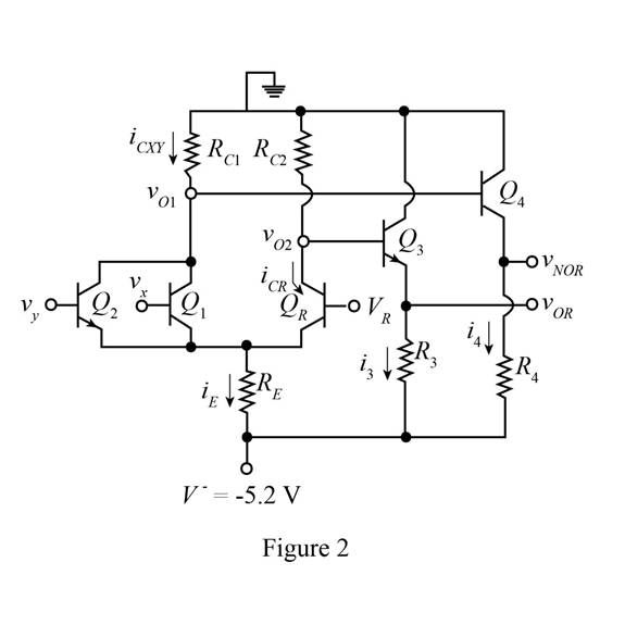
The redesign of the ECL circuit is shown in Figure 2 and the value of resistors are
Explanation of Solution
Calculation:
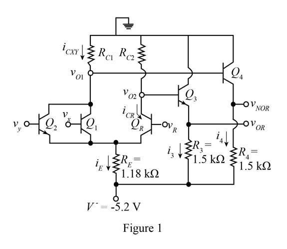
The given diagram is shown in Figure 1
The redesign circuit is shown below.
The required diagram is shown in Figure 2
The expression for
Substitute
If
The expression for
Substitute
Substitute
If
The expression for
Substitute
The expression for
Substitute
Input voltages
Substitute
If
Substitute
The expression for
Substitute
The value of
The expression for
Substitute
The expression for
Substitute
The expression for
Substitute
Conclusion:
Therefore, the redesign of the ECL circuit is shown in Figure 2 and the value of resistors are
Want to see more full solutions like this?
Chapter 17 Solutions
MICROELECT. CIRCUIT ANALYSIS&DESIGN (LL)

- Hin H.W Design 4-bit GPR using as follows: SISO Function 00 01 10 1 1 No operation Arithmetic Shift right Rotate Shift left Incrementarrow_forwardThe gate characteristic of an SCR has a straight-line slope of 125. What should be the gate-source resistance, if the source triggering voltage is 12 V and allowable value of gate power dissipation is 0.65 watts. (a) 450 2 (b) 291.36 2 (c) 41.46 2 (d) 83.54 2arrow_forwardQuestion 2 Incorrect Mark 0.00 out of 1.00 P Flag question In a self-bias n-channel JFET, the operating point is to be set at Ip = 1.5 mA and Vps =10 V. The JFET parameters are IDss= 5 mA and Vp = 2 V. Given that VDD = 20 V. The value of Rs required for the circuit is Select one: a. 60.3 kohms b. 603 ohms c. 60.3 ohms d. 603 kohms Your answer is incorrect. The correct answer is: 603 ohmsarrow_forward
- Draw 8259A interfacing connections with 8086 at the address 0744H.arrow_forwardA 4bits Analog-digital converter with an input voltage signal ranging from (-2V to 2V). Determine the following. 1. Number of Quantization levels with their values 2. Step size. 3. SNR of Quantization 4. Quantization error. 5. Quantization level for the following values of the analog voltage (v=1.4V, -1.3V, 2V)arrow_forward-Design ADC using VTC (Voltage to Time Converter) with clock generator fe=32Hz and the slope of voltage to time converter K= 0.025 and the maximum analog input VA-20V, find 1- Number of bits to design the counter 2- The digital conversion (Binary form) of analog input-17.3V 3- Total conversion time.arrow_forward
- draw curve (Vin & Vout ) in resistor transistor logicarrow_forwardA 12-bit ADC unit has an input voltage range of -ve 5to +ve 5 VDC. What is the minimum difference in voltage required by an analogue signal for the digitally converted value to reflect that change(resolution)? 0.0012V DC b. None of all 0.083V DC C. 0.0024V DC 4arrow_forwardGate terminal of MOSFET has full control on its operation. Select one: O True O Falsearrow_forward
- Consider Analog to Digital Converters, calculate the following for a 3-bit quantizer with a range from -5 to 5 V. a) How many levels does this ADC have? b) Determine the quantization step size c) Determine the quantization error d) In case the accuracy required imposes a quantization error less than 4 mV, what is the specification needed for the used ADC?arrow_forwardThe gate of a JFET is . . biased Select one: a. forward b. reverse as well as forward c. none of the above d. reversearrow_forwardintegrated circuit families (RTL, DTL, TTL, CMOS) 4. Let vx = vy = 0.1V (Logic 0), B = 25 Determine all the currents and voltages in the circuit below: 11, 12, iR, IRC, iB, v1 & vo. Vcc=5 V 84 48 = 4 ΚΩ VI Dx vx H Vy O KH Dy RB = 10 ΚΩ Figure 17.20 Basic diode-transistor logic gate D₁ D2₂ DA IRC VB ≤RC= 14 ΚΩ -OVO loarrow_forward
 Introductory Circuit Analysis (13th Edition)Electrical EngineeringISBN:9780133923605Author:Robert L. BoylestadPublisher:PEARSON
 Delmar's Standard Textbook Of ElectricityElectrical EngineeringISBN:9781337900348Author:Stephen L. HermanPublisher:Cengage Learning
 Programmable Logic ControllersElectrical EngineeringISBN:9780073373843Author:Frank D. PetruzellaPublisher:McGraw-Hill Education
 Fundamentals of Electric CircuitsElectrical EngineeringISBN:9780078028229Author:Charles K Alexander, Matthew SadikuPublisher:McGraw-Hill Education
 Electric Circuits. (11th Edition)Electrical EngineeringISBN:9780134746968Author:James W. Nilsson, Susan RiedelPublisher:PEARSON
 Engineering ElectromagneticsElectrical EngineeringISBN:9780078028151Author:Hayt, William H. (william Hart), Jr, BUCK, John A.Publisher:Mcgraw-hill Education,