
Videos
Synthesize the function
using the op amp circuit shown in Fig. 16.34. Select
Let R1 = 1 kΩ, and determine C1, C2, and R2.
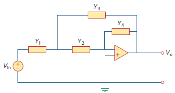
Figure 16.34
Want to see the full answer?
Check out a sample textbook solution
Chapter 16 Solutions
Fundamentals of Electric Circuits


- intransfere funCtion of LTI syste in giving such that (३) = S n S+4 @ find the differential equation describing the system 6 find the output 4() af that system When imput t Xe)=e* UCE)arrow_forwardFor the block diagram shown in Figure Q2(c) Y(s) i) Obtain the overall transfer function, usiny Block Dlagram Reduction method R(s) K;(s) K2(s) Y(s) R(s) G(s) G2(s) G3(s) G4(s) H(s) H2(s)arrow_forwardCanonical Forms. Solve the ff: F(x,y,z) = m0 + m1 + m3 + m6 F(x,y,z) = (M1) (M3) (M7) F(w,x,y,z) = m1 + m3 + m6 + m12 + m15 F(w,x,y,z) = (M3) (M6) (M9)(M11)(M12)(M13) F = x'y'z'+ x'y'z+ x'yz'+ x'yz+ xy'z'+ xyz'+xyz Q = (A+B+C) (A’+B’+C) (A’+B+C’) (A’+B+C)arrow_forward
- x[n]= {3, 0, 0, 0, 3}arrow_forward1. Given input r[n] = 6[n] and an output sequence, y[n] %3D What is the transfer function, h[n]? a. b. If r[n] = 26[n] + 46[n – 1] – 36[n – 2] – 8{n – 3), find y[n] = r{n] ® h[n]. %3D %3Darrow_forwardH.W.@Find the state-transition matrix &(t), Ahe Characteristic equation and eigenvalues of A for the following cases: 30 @ A = [ 33 ], B = [i] -3 (ii) A= ], B = [i] Vin -5 1 C -5 00-5 b) b Use a state variable model to describe the circuit shown belowe obtain the response to an input unit step when the initial current is zero and the initial capacitor voltage is zero R=4_2 L=0.01 H w m 1000 MF Vc T.arrow_forward
- Q1. A simplified version of an automobile or motorcycle suspension system as shown in Figure Q1. Obtain the transfer function Y(s)/U(s) of the system. The input u is a displacement input. m₂ www m₁ ww ü b i Figure Q1arrow_forward4. Given the block diagrams below, what is the transfer function relating input r to output y? What is the characteristic equation of the closed-loop system? Is the system stable? r a) b) + r + 4 5 s + 20 1 Kp + − Ki + ska S 1 2s + 3 s+1 4s² + 10 y 1 ms² + cs + k yarrow_forwardR(s) C(s) G(s) X(s) Select an equation representing the block diagram shown and an equation representing its equivalent block diagram after shifting the G(s) to the left side of summing junction. Select one or more: O a. R(s)-(X(s)/G(s))=(C(s)/G(s)) O b. R(s)-(X(s)/G(s))=G(S)C(s) Oc. R(s)G(s)-X(s)(1/G(s))=C(s) R(s)G(s)-X(s)=C(s) e. R(s)G(s) +X(s)=C(s)arrow_forward
- Q3) Sketch the block diagram representation of the discrete-time system described by the following input-output relation. y(n) = ½ y(n − 1) + ½x(n) + ½¼x(n − 1arrow_forwardReduce the signal flow graph shown in FIGURE Q3 to a single transfer 1. function between the input variable R(s) to the output Y(s), using Mason's rule. 0.5 1 1 3 S R(s) O Y(s) 2.arrow_forwardDevelop a Transfer Function C(s)/R(s) from the following block diagram shown in Figure Q3. H1(s) R(s) Cls) G,(s) G2(s) G3(s) H2(s) H3(s) Figure Q3arrow_forward
 Introductory Circuit Analysis (13th Edition)Electrical EngineeringISBN:9780133923605Author:Robert L. BoylestadPublisher:PEARSON
 Delmar's Standard Textbook Of ElectricityElectrical EngineeringISBN:9781337900348Author:Stephen L. HermanPublisher:Cengage Learning
 Programmable Logic ControllersElectrical EngineeringISBN:9780073373843Author:Frank D. PetruzellaPublisher:McGraw-Hill Education
 Fundamentals of Electric CircuitsElectrical EngineeringISBN:9780078028229Author:Charles K Alexander, Matthew SadikuPublisher:McGraw-Hill Education
 Electric Circuits. (11th Edition)Electrical EngineeringISBN:9780134746968Author:James W. Nilsson, Susan RiedelPublisher:PEARSON
 Engineering ElectromagneticsElectrical EngineeringISBN:9780078028151Author:Hayt, William H. (william Hart), Jr, BUCK, John A.Publisher:Mcgraw-hill Education,