
Mechanics of Materials (10th Edition)
10th Edition
ISBN: 9780134319650
Author: Russell C. Hibbeler
Publisher: PEARSON
expand_more
expand_more
format_list_bulleted
Concept explainers
Videos
Textbook Question
Chapter 14.2, Problem 14.5P
Using bolts of the same material and cross-sectional area, two possible attachments for a cylinder head are shown. Compare the strain energy developed in each case, and then explain which design is better for resisting an axial shock or impact load.
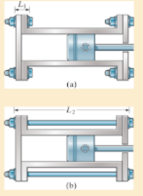
Prob. 14–5
Expert Solution & Answer
Want to see the full answer?
Check out a sample textbook solution
Students have asked these similar questions
The connecting rod of a four stroke cycle Diesel engineis of circular section and of length 550 mm. The diameter and stroke of the cylinder are 150 mm and240 mm respectively. The maximum combustion pressure is 4.7 N/mm2. Determine the diameter ofthe rod to be used, for a factor of safety of 3 with a material having a yield point of 330 MPa.Find also the maximum bending stress in the connecting rod due to whipping action if the engine runsat 1000 r.p.m. The specific weight of the material is 7800 kg/m3. [Ans. 33.2 mm ; 48 MPa]
The angle embraced is 175° and the coefficient of friction between the belt and the
pulley is 0.25. A leather belt is required to transmit 9.5 kW from a pulley 100 cm in
diameter, running at 2500 r.p.m.. If the safe working stress for the leather belt is 2
MPa, density of leather 1000 Kg/m³ and thickness of belt 1 cm, determine the width
of the belt.
Rim of plate
Splined Sleeve
Driving
Shuff
Dhe 11
Doc-A
Thiven
Shuff
The aluminum shell is fully bonded to the brass core, and the assembly is unstressed at a temperature of 78°F. The
temperature of the assembly reaches 190°F. Consider only axial deformations.
1 in.
-2.5 in.
Brass core
E = 15 x 106 psi
a = 11.6 × 10⁻⁶°F
Aluminum shell
E = 10.6 × 10⁶ psi
a = 12.9 x 10⁻⁶°F
Determine stress in the aluminum shell
The stress in the aluminum shell is ____ksi.
Chapter 14 Solutions
Mechanics of Materials (10th Edition)
Ch. 14.2 - A material is subjected to a general state of...Ch. 14.2 - The strain-energy density for plane stress must be...Ch. 14.2 - The A-36 steel bar consists of two segments, one...Ch. 14.2 - Determine the torsional strain energy in the A992...Ch. 14.2 - Using bolts of the same material and...Ch. 14.2 - If P = 60 kN, determine the total strain energy...Ch. 14.2 - Determine the maximum force P and the...Ch. 14.2 - Determine the torsional strain energy in the A992...Ch. 14.2 - Determine the torsional strain energy in the A-36...Ch. 14.2 - The shaft assembly is fixed at C. The hollow...
Ch. 14.2 - Determine the total axial and bending strain...Ch. 14.2 - If P = 10 kip, determine the total strain energy...Ch. 14.2 - Determine the maximum force P and the...Ch. 14.2 - Consider the thin-walled tube of Fig.5-26 . Use...Ch. 14.2 - Determine the bending strain energy in the A992...Ch. 14.2 - Determine the bending strain energy in the beam....Ch. 14.2 - Prob. 14.17PCh. 14.2 - Prob. 14.18PCh. 14.2 - Determine the bending strain energy in the 2-in...Ch. 14.2 - Determine the total strain energy in the steel...Ch. 14.2 - Determine the bending strain energy in the beam....Ch. 14.2 - The bolt has a diameter of 10 mm, and the arm AB...Ch. 14.2 - Determine the bending strain energy in the...Ch. 14.2 - Determine the bending strain energy in the simply...Ch. 14.3 - Determine the vertical displacement of joint D. AE...Ch. 14.3 - Determine the horizontal displacement of joint C....Ch. 14.3 - Determine the horizontal displacement of joint A....Ch. 14.3 - AE is constant. Prob. 1428Ch. 14.3 - Determine the vertical displacement of point C of...Ch. 14.3 - Determine the vertical displacement of end B of...Ch. 14.3 - Determine the vertical displacement of point S on...Ch. 14.3 - EI is constant. Prob. 1432Ch. 14.3 - The A992 steel bars are pin connected at C and D....Ch. 14.3 - The A992 steel bars are pin connected at C. If...Ch. 14.3 - Determine the slope of the beam at the pin support...Ch. 14.3 - The cantilevered beam has a rectangular...Ch. 14.3 - The rod has a circular cross section with a moment...Ch. 14.3 - The rod has a circular cross section with a moment...Ch. 14.3 - Determine the vertical displacement of point B on...Ch. 14.3 - Prob. 14.40PCh. 14.3 - Determine the vertical displacement of end B of...Ch. 14.4 - A bar is 4 m long and has a diameter of 30 mm....Ch. 14.4 - Determine the diameter of a red brass C83400 bar...Ch. 14.4 - Prob. 14.44PCh. 14.4 - The collar has a weight of 50 lb and falls down...Ch. 14.4 - The collar has a weight of 50 lb and falls down...Ch. 14.4 - Prob. 14.47PCh. 14.4 - Prob. 14.48PCh. 14.4 - Prob. 14.49PCh. 14.4 - Prob. 14.50PCh. 14.4 - The A-36 steel bolt is required to absorb the...Ch. 14.4 - Prob. 14.52PCh. 14.4 - The composite aluminum 2014T6 bar is made from two...Ch. 14.4 - The composite aluminum 2014-T6 bar is made from...Ch. 14.4 - When the 100-lb block is at h = 3 ft above the...Ch. 14.4 - If the bar has a diameter of 20 mm, determine the...Ch. 14.4 - The collar has a mass of 5 kg and falls dawn the...Ch. 14.4 - The tugboat has a weight of 120 000 lb and is...Ch. 14.4 - The W10 12 beam is made from A-36 steel and is...Ch. 14.4 - The weight of 175 lb is dropped from a height of 4...Ch. 14.4 - The weight of 175 lb, is dropped from a height of...Ch. 14.4 - Determine the maximum height h from which an 80-lb...Ch. 14.4 - The 80-lb weight is dropped from rest at a height...Ch. 14.4 - The 75-lb block has a downward velocity of 2 ft/s...Ch. 14.4 - The 75-lb block has a downward velocity of 2 ft/s...Ch. 14.4 - Prob. 14.66PCh. 14.4 - The overhang beam is made of 2014T6 aluminum....Ch. 14.4 - If the beam is a W1015, determine the maximum...Ch. 14.4 - If the maximum allowable bending stress for the...Ch. 14.4 - A 40-lb weight is dropped from a height of h = 2...Ch. 14.4 - The car bumper is made of...Ch. 14.6 - Determine the vertical displacement of joint A....Ch. 14.6 - Determine the horizontal displacement of joint B....Ch. 14.6 - Determine the vertical displacement of joint B....Ch. 14.6 - Determine the vertical displacement of joint B....Ch. 14.6 - Determine the vertical displacement of joint E....Ch. 14.6 - Determine the horizontal displacement of joint B....Ch. 14.6 - Determine the vertical displacement of joint B....Ch. 14.6 - Determine the horizontal displacement of joint B...Ch. 14.6 - Determine the vertical displacement of joint C of...Ch. 14.6 - Determine the horizontal displacement of joint C....Ch. 14.6 - Determine the vertical displacement of joint D....Ch. 14.6 - Determine the vertical displacement of joint A....Ch. 14.6 - The truss is made from A992 steel rods having a...Ch. 14.6 - Determine the horizontal displacement of joint D....Ch. 14.6 - Determine the horizontal displacement of joint E....Ch. 14.7 - Determine the displacement at point C. El is...Ch. 14.7 - The beam is made of southern pine for which Ep =...Ch. 14.7 - Determine the displacement at point C. El is...Ch. 14.7 - Determine the slope at point C. El is constant....Ch. 14.7 - Determine the slope at point A. El is constant....Ch. 14.7 - Determine the displacement of point C of the beam...Ch. 14.7 - Determine the slope at B of the beam made from...Ch. 14.7 - The beam is made of Douglas fir. Determine the...Ch. 14.7 - Determine the displacement at pulley B. The A992...Ch. 14.7 - The A992 steel beam has a moment of inertia of I =...Ch. 14.7 - The A992 steel beam has a moment of inertia of I =...Ch. 14.7 - The A992 structural steel beam has a moment of...Ch. 14.7 - Determine the displacement at point C of the...Ch. 14.7 - Determine the slope at A of the shaft. El is...Ch. 14.7 - Determine the slope of end C of the overhang beam....Ch. 14.7 - Determine the displacement of point D of the...Ch. 14.7 - Determine the slope at A of the 2014T6 aluminum...Ch. 14.7 - Prob. 14.104PCh. 14.7 - Prob. 14.105PCh. 14.7 - Determine the displacement at point C of the W14 ...Ch. 14.7 - Determine the slope at A of the W14 26 beam made...Ch. 14.7 - Determine the slope at A. El is constant. Prob....Ch. 14.7 - Determine the slope at C of the overhang white...Ch. 14.7 - Determine the displacement at point D of the...Ch. 14.7 - Determine the maximum deflection of the beam...Ch. 14.7 - The beam is made of oak, for which Eo = 11 GPa....Ch. 14.7 - Determine the slope of the shaft at the bearing...Ch. 14.7 - Determine the horizontal and vertical...Ch. 14.7 - Beam AB has a square cross section of 100 mm by...Ch. 14.7 - Beam AB has a square cross section of 100 mm by...Ch. 14.7 - Bar ABC has a rectangular cross section of 300 mm...Ch. 14.7 - Bar ABC has a rectangular cross section of 300 mm...Ch. 14.7 - The L-shaped frame is made from two segments, each...Ch. 14.7 - The L-shaped frame is made from two segments, each...Ch. 14.7 - Determine the vertical displacement of the ring at...Ch. 14.7 - Determine the horizontal displacement at the...Ch. 14.9 - Solve Prob. 1473 using Castiglianos theorem. 1473....Ch. 14.9 - Solve Prob. 1474 using Castiglianos theorem. 1474....Ch. 14.9 - Prob. 14.125PCh. 14.9 - Prob. 14.126PCh. 14.9 - Prob. 14.127PCh. 14.9 - Solve Prob. 1478 using Castiglianos theorem. 1478....Ch. 14.9 - Solve Prob. 1481 using Castiglianos theorem. 1481....Ch. 14.9 - Solve Prob. 1482 using Castiglianos theorem. 1482....Ch. 14.9 - Solve Prob. 1485 using Castiglianos theorem. 1485....Ch. 14.9 - Solve Prob. 1486 using Castiglianos theorem. 1486....Ch. 14.10 - Solve Prob. 1490 using Castiglianos theorem. 1490....Ch. 14.10 - Solve Prob. 1491 using Castiglianos theorem. 1491....Ch. 14.10 - Prob. 14.135PCh. 14.10 - Solve Prob. 1493 using Castiglianos theorem. 1493....Ch. 14.10 - Solve Prob. 1495 using Castiglianos theorem. 1495....Ch. 14.10 - Solve Prob. 1496 using Castiglianos theorem. 1496....Ch. 14.10 - Prob. 14.139PCh. 14.10 - Prob. 14.140PCh. 14.10 - Prob. 14.141PCh. 14.10 - Solve Prob. 14119 using Castiglianos theorem....Ch. 14.10 - Prob. 14.143PCh. 14.10 - Solve Prob. 14105 using Castiglianos theorem....Ch. 14 - A = 2300 mm2, I = 9.5(106) mm4. R141Ch. 14 - If the spring at B has a stiffness k = 200 kN/m....Ch. 14 - The spring at B has a stiffness k = 200 kN/m....Ch. 14 - If they each have a diameter of 30 mm, determine...Ch. 14 - and a length of 10 in. It is struck by a hammer...Ch. 14 - Determine the total axial and bending strain...Ch. 14 - The truss is made from A992 steel rods each having...Ch. 14 - The truss is made from A992 steel rods each having...Ch. 14 - El is constant. Use the method of virtual work....Ch. 14 - using Castiglianos theorem. R149. The cantilevered...
Additional Engineering Textbook Solutions
Find more solutions based on key concepts
The moment of inertia Iy for the slender rod in terms of the rod’s total mass m .
Engineering Mechanics: Statics & Dynamics (14th Edition)
Convert the following quantities from English to SI units: a. 98 Btu/(hr-ft-F) b. 0.24 Btu/(lbm-F) C. 0.04 Ibm/...
Heating Ventilating and Air Conditioning: Analysis and Design
A nozzle at A discharges water with an initial velocity of 36 ft/s at an angle with the horizontal. Determine ...
Vector Mechanics for Engineers: Dynamics
A windowmounted air conditioner removes 3.5kJ from the inside of a home using 1.75 kJ work input. How much ener...
EBK FUNDAMENTALS OF THERMODYNAMICS, ENH
Comprehension Check 7-14
The power absorbed by a resistor can be given by P = I2R, where P is power in units of...
Thinking Like an Engineer: An Active Learning Approach (3rd Edition)
How is the hydrodynamic entry length defined for flow in a pipe? Is the entry length longer in laminar or turbu...
Fluid Mechanics Fundamentals And Applications
Knowledge Booster


Learn more about
Need a deep-dive on the concept behind this application? Look no further. Learn more about this topic, mechanical-engineering and related others by exploring similar questions and additional content below.Similar questions
- The gas storage tank is fabricated by bolting together two half cylindrical thin shells and two hemispherical shells as shown. If the tank wall has a thickness of 50 mm for cylindrical and hemispherical shells, The bolts were installed as 40 bolts/meter. The tank and the 25 mm diameter bolts are made from material having an allowable normal stress of 150 MPa and 250 MPa, respectively. The tank has an inner diameter of 4 m. What is the maximum pressure that tank can contain.arrow_forwardMo-200j + 400k The 30 kg block is supported by two springs having the stiffness shown. Determine the strech of spring AB, S(AB): 0.4 m 0.3 m 0.4 m Aac 15 Nm A12 AN/m Select one: Oa S(AB) = 0.22 m 6. S(AB) = 0.5 m S(AB) 0.175 m SCAB)-0.12 m Temeriude of the moment produced by force F about segment AB of the pipe assembly is eaual to.arrow_forwardSituation 1: A-D A W14X120 is used as a tension member in atruss. The flanges of the member are connected to a gusset plate by ¾ inch boltas shown below. Use A36 steel with Fy=36 ksi and Fu=58 ksi Properties and Dimension Ag=35.30 in^2 rx = 6.24 in ry = 3.74 in d=14.5 in tf=0.94 in bf=14.7 in tw=0.59 in Y k1=1.5 k=1.54 I tf=0.94 d=14.5 tw=0.59 bf=14.7 A. Determine the Yielding Capacity of the section based on LRFD (kips) Round your answer to 2 decimal places. From Situation 1: b. Determine the effective net area of the section. For shear lag Factor U used the recommended values depending on the dimension of the section for W shapes with 3 or more fasteners per line. Note: use hole diameter if bf < d;U=0.85 else U =0.9 3 Round your answer to 3 decimal places. From Situation 1: c. Determine the Tensile Rupture capacity of the section based on LRFD From Situation 1: d. Determine the Demand to Governing Capacity Ratio (based on yielding and rupture only) if the Demand load carried by the…arrow_forward
- A locomotive semi-elliptical laminated spring has an overall length of 1.5 m and sustains a load of 85 KN at its center. The spring has 4 full length leaves and 11 graduated leaves with a central band of 102 mm width. All the leaves are to be stressed to 460 MPa, when fully loaded.The ratio of the total spring depth to that of width is 3. E = 210 KN/mm^2. Determine 1. The thickness and width of the leaves. O t= 15.58 mm, b = 80.48 mm t= 20.435 mm, b 87.98 mm O t= 17.29 mm, b = 86.45 mm 2. The initial gap that should be provided between the full length and graduated leaves before the band load is applied. * C = 22.302 mm C = 20.625 mm C = 18.093 mmarrow_forwardThe connection between an electric motor and a construction machine shaft is provided by means of a rigid coupling with flanges, through which the moment is transferred via the coupling flanges.The power of the electric motor is 35kw and the speed is 870rpm. The coupling flanges are connected with three bolts of quality 5.6 with a placement diameter of 40 mm.The surface pressure safety stress for bolts is 16 MPa. The contact length of the bolt with the coupling flange is 12 mm. The coefficient of friction on the flange surfaces is 0.14; the operating factor for the coupling is 0.8. The working conditions of the contact element, the material properties are very well known; since force and stress analyses can be performed with high accuracy,; question) Determine the bolt that should be used in the clutch from the table.arrow_forwardA locomotive semi-elliptical laminated spring has an overall length of 1.5 m and sustains a load of 85 KN at its center. The spring has 4 full length leaves and 11 graduated leaves with a central band of 102 mm width. All the leaves are to be stressed to 460 MPa, when fully loaded.The ratio of the total spring depth to that of width is 3. E = 210 KN/mm^2. Determine 1. The thickness and width of the leaves. * 2. The initial gap that should be provided between the full length and graduated leaves before the band load is applied. 3. The load exerted on the band after the spring is assembledarrow_forward
- A 75 mm long billet that has a 35 mm diameter is reduced to a diameter of 20 mm through direct extrusion. If o= 750 e025 MPa in the stress strain relationship for the wire material, determine the ram pressure.arrow_forwardA railway car wheel rolls on a rail. Both rail and wheel are made of steel for which E = 210 GPa and v= 0.3. The wheel has a radius of R₁ = 0.4 m, and the cross radius of the rail top surface is R₂ = 0.3 m (Fig. 13-14). Determine the size of the contact area and the maximum contact pressure if compressive load P is 90 kN. PI R ₂ RI Fig. 13.14.arrow_forwardThe aluminum shell is fully bonded to the brass core, and the assembly is unstressed at a temperature of 78°F. The temperature of the assembly reaches 205°F. Consider only axial deformations. 1 in. Brass core E = 15 x 10° psi a = 11.6 x 10-/0F Aluminum shell E = 10.6 x 10° psi a = 12.9 x 10-%°F - 2.5 in.- Determine the stress in the brass core. The stress in the brass core is ksi.arrow_forward
- A locomotive semi-elliptical laminated spring has an overall length of 1 m and sustains a load of 70 kN at its center. The spring has 3 full length leaves and 15 graduated leaves with a central band of 100 mm width. All the leaves are to be stressed to 400 MPa, when fully loaded. The ratio of the total spring depth to that of width is 2. E = 210 kN/mm2. Determine the thickness and width of the leaves t = 11.64 mm & W = 109 mm t = 11.14 mm & W 103 mm O t = 11.94 mm & W = 118 mm O t = 11.34 mm & W = 108 mm t = 11.14 mm & W = 118 mm Oarrow_forwardTo function a hacksaw requires pre-tensioning of the blade. The blade must have a high enough pre-tension that it does not buckle in use, but not so high that the frame becomes permanently deformed (i.e., yields plastically). Determine the maximum blade pre-tension if the frame is not to exceed a yield stress of 48 ksi. b= 0.1875 in l = 0.62510 0.625 in. 4 in. Framearrow_forward- 2 m 1 m- - 2 m D www ww wwwww 1.5 m k = 100 N/m k = 100 N/m %3D A Determine the mass of each of the two cylinders if they cause a sag of s = 0.5 m when suspended from the rings at A and B, Note that s = 0 when the cylinders are removed. (Draw the free body diagram)arrow_forward
arrow_back_ios
SEE MORE QUESTIONS
arrow_forward_ios
Recommended textbooks for you
 Elements Of ElectromagneticsMechanical EngineeringISBN:9780190698614Author:Sadiku, Matthew N. O.Publisher:Oxford University Press
 Mechanics of Materials (10th Edition)Mechanical EngineeringISBN:9780134319650Author:Russell C. HibbelerPublisher:PEARSON
 Thermodynamics: An Engineering ApproachMechanical EngineeringISBN:9781259822674Author:Yunus A. Cengel Dr., Michael A. BolesPublisher:McGraw-Hill Education
 Control Systems EngineeringMechanical EngineeringISBN:9781118170519Author:Norman S. NisePublisher:WILEY
 Mechanics of Materials (MindTap Course List)Mechanical EngineeringISBN:9781337093347Author:Barry J. Goodno, James M. GerePublisher:Cengage Learning
 Engineering Mechanics: StaticsMechanical EngineeringISBN:9781118807330Author:James L. Meriam, L. G. Kraige, J. N. BoltonPublisher:WILEY
Elements Of Electromagnetics
Mechanical Engineering
ISBN:9780190698614
Author:Sadiku, Matthew N. O.
Publisher:Oxford University Press
Mechanics of Materials (10th Edition)
Mechanical Engineering
ISBN:9780134319650
Author:Russell C. Hibbeler
Publisher:PEARSON
Thermodynamics: An Engineering Approach
Mechanical Engineering
ISBN:9781259822674
Author:Yunus A. Cengel Dr., Michael A. Boles
Publisher:McGraw-Hill Education
Control Systems Engineering
Mechanical Engineering
ISBN:9781118170519
Author:Norman S. Nise
Publisher:WILEY
Mechanics of Materials (MindTap Course List)
Mechanical Engineering
ISBN:9781337093347
Author:Barry J. Goodno, James M. Gere
Publisher:Cengage Learning
Engineering Mechanics: Statics
Mechanical Engineering
ISBN:9781118807330
Author:James L. Meriam, L. G. Kraige, J. N. Bolton
Publisher:WILEY
Material Properties 101; Author: Real Engineering;https://www.youtube.com/watch?v=BHZALtqAjeM;License: Standard YouTube License, CC-BY