
Shigley's Mechanical Engineering Design (McGraw-Hill Series in Mechanical Engineering)
10th Edition
ISBN: 9780073398204
Author: Richard G Budynas, Keith J Nisbett
Publisher: McGraw-Hill Education
expand_more
expand_more
format_list_bulleted
Concept explainers
Videos
Textbook Question
Chapter 13, Problem 32P
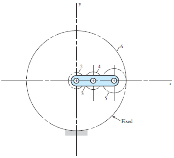
The 24T 6-pitch 20° pinion 2 shown in the figure rotates clockwise at 1000 rev/min and is driven at a power of 25 hp. Gears 4, 5, and 6 have 24, 36, and 144 teeth, respectively. What torque can arm 3 deliver to its output shaft? Draw free-body diagrams of the arm and of each gear and show all forces that act upon them.
Problem 13–32
Expert Solution & Answer

Trending nowThis is a popular solution!

Students have asked these similar questions
The 24T 6-pitch 20° pinion 2 shown in the figure rotates clockwise at 900
rev/min and is driven at a power of 28 hp. Gears 4, 5, and 6 have 24, 36,
and 144 teeth, respectively.
NOTE: This is a multi-part question. Once an answer is submitted, you will
be unable to return to this part.
Fixed
What torque can arm 3 deliver to its output shaft?
The torque that arm 3 delivers to its output shaft is
lbf-in.
The figure shows a pair of shaft-mounted spur gears having a diametral pitch of 5 teeth/in with an 18-tooth
20° pinion driving a 45-tooth gear. The power input is 28-hp at 1700 rev/min. Find the magnitude of the
force acting on bearing D.
3
2
3 in 3 in
The magnitude of the force acting on bearing Dis
lbf.
13-32
The 247 6-pitch 20° pinion 2 shown in the figure rotates clockwise at 1000 rev/min and is driven at a power of 25 hp. Gears 4, 5, and 6 have 24, 36, and 144 teeth, respectively. What torque can arm 3 deliver to its output shaft? Draw free-body diagrams of the arm and of each gear and show all forces that act upon them.
Chapter 13 Solutions
Shigley's Mechanical Engineering Design (McGraw-Hill Series in Mechanical Engineering)
Ch. 13 - A 17-tooth spur pinion has a diametral pitch of 8...Ch. 13 - A 15-tooth spur pinion has a module of 3 mm and...Ch. 13 - A spur gearset has a module of 6 mm and a velocity...Ch. 13 - A 21-tooth spur pinion mates with a 28-tooth gear....Ch. 13 - A 20 straight-tooth bevel pinion having 14 teeth...Ch. 13 - A parallel helical gearset uses a 20-tooth pinion...Ch. 13 - A parallel helical gearset consists of a 19-tooth...Ch. 13 - To avoid the problem of interference in a pair of...Ch. 13 - Prob. 9PCh. 13 - Prob. 10P
Ch. 13 - Prob. 11PCh. 13 - Prob. 12PCh. 13 - Prob. 13PCh. 13 - Prob. 14PCh. 13 - A parallel-shaft gearset consists of an 18-tooth...Ch. 13 - The double-reduction helical gearset shown in the...Ch. 13 - Shaft a in the figure rotates at 600 rev/min in...Ch. 13 - The mechanism train shown consists of an...Ch. 13 - The figure shows a gear train consisting of a pair...Ch. 13 - A compound reverted gear trains are to be designed...Ch. 13 - Prob. 21PCh. 13 - Prob. 22PCh. 13 - Prob. 23PCh. 13 - A gearbox is to be designed with a compound...Ch. 13 - The tooth numbers for the automotive differential...Ch. 13 - Prob. 26PCh. 13 - In the reverted planetary train illustrated, find...Ch. 13 - Prob. 28PCh. 13 - Tooth numbers for the gear train shown in the...Ch. 13 - The tooth numbers for the gear train illustrated...Ch. 13 - Shaft a in the figure has a power input of 75 kW...Ch. 13 - The 24T 6-pitch 20 pinion 2 shown in the figure...Ch. 13 - The gears shown in the figure have a module of 12...Ch. 13 - The figure shows a pair of shaft-mounted spur...Ch. 13 - Prob. 35PCh. 13 - Prob. 36PCh. 13 - A speed-reducer gearbox containing a compound...Ch. 13 - For the countershaft in Prob. 3-72, p. 152, assume...Ch. 13 - Prob. 39PCh. 13 - Prob. 40PCh. 13 - Prob. 41PCh. 13 - Prob. 42PCh. 13 - The figure shows a 16T 20 straight bevel pinion...Ch. 13 - The figure shows a 10 diametral pitch 18-tooth 20...Ch. 13 - Prob. 45PCh. 13 - The gears shown in the figure have a normal...Ch. 13 - Prob. 47PCh. 13 - Prob. 48PCh. 13 - Prob. 49PCh. 13 - The figure shows a double-reduction helical...Ch. 13 - A right-hand single-tooth hardened-steel (hardness...Ch. 13 - The hub diameter and projection for the gear of...Ch. 13 - A 2-tooth left-hand worm transmits 34 hp at 600...
Knowledge Booster


Learn more about
Need a deep-dive on the concept behind this application? Look no further. Learn more about this topic, mechanical-engineering and related others by exploring similar questions and additional content below.Similar questions
- Question 1: The figure shows a 16T 20° straight bevel pinion driving a 32T gear, and the location of the bearing centerlines. Pinion shaft a receives 2.5 hp at 248 rev/min. Determine the bearing reactions at A and B if A is to take both radial and thrust loads. On-Screen Keyboard Esc 1 3. 4 5 6.arrow_forward13-31 Shaft a in the figure has a power input of 75 kW at a speed of 1000 rev/min in the counterclock- wise direction. The gears have a module of 5 mm and a 20° pressure angle. Gear 3 is an idler. (a) Find the force F3, that gear 3 exerts against shaft b. (b) Find the torque T4, that gear 4 exerts on shaft c. 517 34T Problem 13-31 3 177arrow_forwardProblem 13.049 - Bearing Reactions for Beveled Gears The figure shows a 16T 20° straight bevel pinion driving a 32 T gear and the location of the bearing centerlines. Pinion shaft a receives 2 hp at 200 rev/min. Determine the bearing reactions at A if it is to take both radial and thrust loads. Problem 13-43 Dimensions in inches. The bearing reaction due to radial load FA, radial is | B 4 Ibf and the bearing reaction due to thrust load FA, thrust is Ibf.arrow_forward
- a in the figure has a power input of 75 kW at a speed of 1000 rev/min in the counterclock- wise direction. The gears have a module of 5 mm and a 20° pressure angle. Gear 3 is an idler. (a) Find the force F3b that gear 3 exerts against shaft b. (b) Find the torque T4c that gear 4 exerts on shaftarrow_forward187 13-40 The figure shows a pair of shaft-mounted spur gears having a diametral pitch of 5 teeth/in with an 18-tooth 20° pinion driving a 45-tooth gear. The power input is 32-hp at 1800 rev/min. Find the direction and magnitude of the forces acting on bearings A, B, C, and D. 13-41 The figure shows the electric-motor frame dimensions for a 30-hp 900 rev/min motor. The frame is bolted to its support using four -in bolts spaced 11 in apart in the view shown and 14 in apart when viewed from the end of the motor. A 4 diametral pitch 20° spur pinion having 20 teeth and a face width of 2 in is keved to and fluch with 3 in 3 in Problem 13-40arrow_forward13-55 Gear 2, in the figure, has 16 teeth, a 20° transverse pressure angle, a 15° helix angle, and a module of 4 mm. Gear 2 drives the idler on shaft b, which has 36 teeth. The driven gear on shaft c has 28 teeth. If the driver rotates at 1600 rev/min and transmits 6 kW, find the radial and thrust load on each shaft. LH 90° Problem 13-55 RH RHarrow_forward
- Problem 4. A 16-tooth 240 Bhn steel spur pinion having a pressure angle of 20° and rotating at 720 rev/min drives a 28-tooth 240 Bhn steel gear having a 2.5 -in face and a diametral pitch of 5 teeth/in. Find the factor of safety of this drive based on bending strength if 17.5 hp is transmitted. Use Ko=Ks=1, Km=1.6 and Qv=7.arrow_forward13-33 The gears shown in the figure have a diametral pitch of 2 teeth per inch and a 20° pressure angl The pinion rotates at 1800 rev/min clockwise and transmits 200 hp through the idler pair to gear 5 on shaft c. What forces do gears 3 and 4 transmit to the idler shaft? Problem 13-33 187 327 187 5 W-487arrow_forwardThe four helical gears shown in figure have a module in the normal plane of 4 mm and a pressure angle in the normal plane of 0.35 rad. The motor shaft rotates 550 rpm and transmits 20 kW. Other data are on the drawing. (a) What is the speed ratio between the motor (input) and output shafts? (b) Determine all force components that the 20-tooth pinion applies to the 50-tooth gear. Make a sketch showing these forces applied to the gear. (c) The same as part (b), except for the force components that the 50-tooth gear exerts on the 25- tooth pinion 100 50 teeth 200 125 25 teeth ψ = 0.35 rad right hand Motor 20 teeth ψ = 0.50 rad left hand 50 teeth Outputarrow_forward
- For the gear mechanism in the figure: P1 = 4 kW, η1 = 1000 rpm, z1 = 18, z2 = 36, z3 = 54, z4 = 108, z1 is the driving gear. Total efficiency values for each stage; Since η12 = η34 = 0.96; Find the output torque and speed of gear z4.arrow_forwardThe figure shows a double-reduction helical gearset. Pinion 2 is the driver, and it receives a torque of 1200 Ibf • in from its shaft in the direction shown. Pinion 2 has a normal diametral pitch of 8 teeth/in, 14 teeth, and a normal pressure angle of 20° and is cut right-handed with a helix angle of 30°. The mating gear 3 on shaft b has 36 teeth. Gear 4, which is the driver for the second pair of gears in the train, has a normal diametral pitch of 3 teeth/in, 15 teeth, and a normal pressure angle of 20° and is cut left-handed with a helix angle of 15°. Mating gear S has 45 teeth. Find the magnitude and direction of the force exerted by the bearings C and D on shaft b if bearing C can take only a radial load while bearing D is mounted to take both radial and thrust loads.arrow_forward13-39 The gears shown in the figure have a module of 12 mm and a 20° pressure angle. The pinion rotates at 1800 rev/min clockwise and transmits 150 kW through the idler pair to gear 5 on shaft c. What forces do gears 3 and 4 transmit to the idler shaft? w487 187 Problem 13-39 16 327 187arrow_forward
arrow_back_ios
SEE MORE QUESTIONS
arrow_forward_ios
Recommended textbooks for you
 Elements Of ElectromagneticsMechanical EngineeringISBN:9780190698614Author:Sadiku, Matthew N. O.Publisher:Oxford University Press
 Mechanics of Materials (10th Edition)Mechanical EngineeringISBN:9780134319650Author:Russell C. HibbelerPublisher:PEARSON
 Thermodynamics: An Engineering ApproachMechanical EngineeringISBN:9781259822674Author:Yunus A. Cengel Dr., Michael A. BolesPublisher:McGraw-Hill Education
 Control Systems EngineeringMechanical EngineeringISBN:9781118170519Author:Norman S. NisePublisher:WILEY
 Mechanics of Materials (MindTap Course List)Mechanical EngineeringISBN:9781337093347Author:Barry J. Goodno, James M. GerePublisher:Cengage Learning
 Engineering Mechanics: StaticsMechanical EngineeringISBN:9781118807330Author:James L. Meriam, L. G. Kraige, J. N. BoltonPublisher:WILEY
Elements Of Electromagnetics
Mechanical Engineering
ISBN:9780190698614
Author:Sadiku, Matthew N. O.
Publisher:Oxford University Press
Mechanics of Materials (10th Edition)
Mechanical Engineering
ISBN:9780134319650
Author:Russell C. Hibbeler
Publisher:PEARSON
Thermodynamics: An Engineering Approach
Mechanical Engineering
ISBN:9781259822674
Author:Yunus A. Cengel Dr., Michael A. Boles
Publisher:McGraw-Hill Education
Control Systems Engineering
Mechanical Engineering
ISBN:9781118170519
Author:Norman S. Nise
Publisher:WILEY
Mechanics of Materials (MindTap Course List)
Mechanical Engineering
ISBN:9781337093347
Author:Barry J. Goodno, James M. Gere
Publisher:Cengage Learning
Engineering Mechanics: Statics
Mechanical Engineering
ISBN:9781118807330
Author:James L. Meriam, L. G. Kraige, J. N. Bolton
Publisher:WILEY
Power Transmission; Author: Terry Brown Mechanical Engineering;https://www.youtube.com/watch?v=YVm4LNVp1vA;License: Standard Youtube License