
Mechanics of Materials (MindTap Course List)
9th Edition
ISBN: 9781337093347
Author: Barry J. Goodno, James M. Gere
Publisher: Cengage Learning
expand_more
expand_more
format_list_bulleted
Concept explainers
Videos
Textbook Question
Chapter 10, Problem 10.5.1P
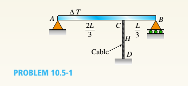
A cable CD of a length H is attached to the third point of a simple beam AB of a length L (see figure). The moment of inertia of the beam is I, and the effective cross-sectional area of the cable is A. The cable is initially taut but without any initial tension,
(a)
Obtain a formula for the tensile force S in the
cable when the temperature drops uniformly by
(b)
Repeat part (a), assuming a wood beam and
steel cable.
Expert Solution & Answer

Trending nowThis is a popular solution!

Students have asked these similar questions
A 1,400-N uniform boom at o
= 58.5° to the horizontal is supported by a cable at an angle 0 = 31.5° to the horizontal as
shown in the figure below. The boom is pivoted at the bottom, and an object of weight w = 1,850 N hangs from its top.
w
Pivot
(a) Find the tension in the support cable.
kN
(b) Find the components of the reaction force exerted by the pivot on the boom. (Assume the positive x-direction is
to the right and the positive y-direction is upward. Include the sign of the value in your answer.)
horizontal component
kN
vertical component
kN
A 1,400-N uniform boom at o = 61.0° to the horizontal is supported by a cable at an angle e = 29.0° to the horizontal as shown in the figure below. The boom is pivoted at the bottom,
and an object of weight w = 1,750 N hangs from its top.
w
Pivot
(a) Find the tension in the support cable.
kN
(b) Find the components of the reaction force exerted by the pivot on the boom. (Assume the positive x-direction is to the right and the positive y-direction is upward. Include the
sign of the value in your answer.)
horizontal component
kN
vertical component
kN
The beam in the figure below is subjected to a load P= 3.9 kN at its end. Young's modulus is 210 GPa and the moment of inertia for the beam's cross-section is 5×106 mm².
P
A
|×-|
a
B
1x₂.
b
If a 1.5 m and b= 1.3 m, determine:
a) Reaction value at support A. Positive direction is considered upwards. Enter your answer in kN to 2 decimal places.
Jvc
Chapter 10 Solutions
Mechanics of Materials (MindTap Course List)
Ch. 10 - A propped cantilever steel beam is constructed...Ch. 10 - A fixed-end b earn is subjected to a point load at...Ch. 10 - A propped cantilever beam AB of a length L is...Ch. 10 - A fixed-end beam AB of a length L supports a...Ch. 10 - A cantilever beam AB of a length L has a fixed...Ch. 10 - A cantilever beam of a length L and loaded by a...Ch. 10 - A cantilever beam has a length L and is loaded by...Ch. 10 - A propped cantilever beam of a length L is loaded...Ch. 10 - A propped cantilever beam of a length L is loaded...Ch. 10 - A fixed-end beam of a length L is loaded by a...
Ch. 10 - A fixed-end b earn of a length L is loaded by a...Ch. 10 - A fixed-end beam of a length L is loaded by...Ch. 10 - A counterclockwise moment M0acts at the midpoint...Ch. 10 - A propped cantilever beam of a length L is loaded...Ch. 10 - A propped cantilever beam is subjected to uniform...Ch. 10 - Repeat Problem 10.3-15 using L = 3.5 m, max = 3...Ch. 10 - A two-span, continuous wood girder (E = 1700 ksi)...Ch. 10 - A fixed-end beam AB carries point load P acting at...Ch. 10 - A fixed-end beam AB supports a uniform load of...Ch. 10 - -4-4 A cantilever beam is supported at B by cable...Ch. 10 - A propped cantilever beam AB of a length L carries...Ch. 10 - A beam with a sliding support at B is loaded by a...Ch. 10 - A propped cantilever beam of a length 2L with a...Ch. 10 - The continuous frame ABC has a pin support at /l,...Ch. 10 - The continuous frame ABC has a pin support at A,...Ch. 10 - Beam AB has a pin support at A and a roller...Ch. 10 - The continuous frame ABCD has a pin support at B:...Ch. 10 - Two flat beams AB and CD, lying in horizontal...Ch. 10 - -4-13 A propped cantilever beam of a length 2L is...Ch. 10 - A propped cantilever beam of a length 2L is loaded...Ch. 10 - Determine the fixed-end moments (MAand MB) and...Ch. 10 - A continuous beam ABC wit h two unequal spans, one...Ch. 10 - Beam ABC is fixed at support A and rests (at point...Ch. 10 - A propped cantilever beam has flexural rigidity EI...Ch. 10 - A triangularly distributed 1oad with a maximum...Ch. 10 - A fixed-end beam is loaded by a uniform load q =...Ch. 10 - Uniform load q = 10 lb/ft acts over part of the...Ch. 10 - A propped cantilever beam with a length L = 4 m is...Ch. 10 - A cant i levé r b ea m i s supported by a tie rod...Ch. 10 - The figure shows a nonprismatic, propped...Ch. 10 - A beam ABC is fixed at end A and supported by beam...Ch. 10 - A three-span continuous beam A BCD with three...Ch. 10 - A beam rests on supports at A and B and is loaded...Ch. 10 - A propped cantilever beam is subjected to two...Ch. 10 - A propped cantilever beam is loaded by a...Ch. 10 - A fixed-end beam AB of a length L is subjected to...Ch. 10 - A temporary wood flume serving as a channel for...Ch. 10 - Two identical, simply supported beams AB and CD...Ch. 10 - The cantilever beam AB shown in the figure is an...Ch. 10 - The beam AB shown in the figure is simply...Ch. 10 - The continuous frame ABC has a fixed support at A,...Ch. 10 - The continuous frame ABC has a pinned support at...Ch. 10 - A wide-flange beam ABC rests on three identical...Ch. 10 - A fixed-end beam AB of a length L is subjected to...Ch. 10 - A beam supporting a uniform load of intensity q...Ch. 10 - A thin steel beam AB used in conjunction with an...Ch. 10 - Find an expression for required moment MA(in terms...Ch. 10 - Repeat Problem 10.4-41 for the loading shown in...Ch. 10 - A propped cantilever beam is loaded by two...Ch. 10 - A cable CD of a length H is attached to the third...Ch. 10 - A propped cantilever beam, fixed at the left-hand...Ch. 10 - Solve t he preceding problem by integrating the...Ch. 10 - A two-span beam with spans of lengths L and L/3 is...Ch. 10 - Solve the preceding problem by integrating the...Ch. 10 - Assume that the deflected shape of a beam AB with...Ch. 10 - (a) A simple beam AB with length L and height h...
Knowledge Booster


Learn more about
Need a deep-dive on the concept behind this application? Look no further. Learn more about this topic, mechanical-engineering and related others by exploring similar questions and additional content below.Similar questions
- AT-shape beam is a load-bearing structure. The top of the T-shape cross section serves as a flange or compression member in resisting compressive stresses. In a building construction, the T-Shape beam which made of an elastic perfectly plastic material was used and its dimension is shown in Figure 3.2. For the beam indicated, determine the fully plastic moment and shape factor of the beam if the value of E = 200 GPa and o, = 250 MPa. (Use moment inertia for the cross section, I = 2600 x 10° m*) 60 mm 20 mm 60 mm 20 mm Figure 3.2 Beam cross-sectionarrow_forwardFigure Q2 shows the free body diagram of a 10 m long beam AD of uniform cross-section, simply supported at locations A and C. A uniformly distributed load of 10 kN/m is applied on the part AB of the beam together with a concentrated load of 20 kN at the end D. 10KN/m 20kN 4m 4m 2m X Fig.Q2: Structural Beam (a) Draw a free body diagram and find the reaction forces at the supports A and C. (b) Draw the shear force diagram (SFD) for the beam and show the values at A, B, C and D. (c) Draw the bending moment diagram (BMD) and show the values at A, B, C and D. 4. (d) From the SFD drawn in (b), find the distance from point A to the position between points A and B where there is no shear and determine the bending moment at that position. 5. (e) Write the mathematical expression for shear force V at section X-X between the points B and C which is at distance x measured from support A.arrow_forward1. Below on the left you can see a cantilever beam (of structural steel, E = 210 GPa), which is fixed to a wall at C and loaded by a force F=6kN at an angle a=45°. The magnitude and angle of the force as well as dimensions a=2.5m and d=4m. On the right side of the beam picture you can see its cross-section, which has been parametrized by height h=130mm, width b=160mm and thicknesses t₁ =9mm and tw = 5mm(flange and web, respectively). Six points E, F, G, H, I and K have also been marked in the cross-section - starting alphabetically from the top. a) Calculate the support reactions at C and draw normal force-, shear- and moment diagrams. b) Calculate the displacement of D in horizontal direction. In the following sections, feel free to take advantage of symmetry as much as you can! please collate your results for each section in a table. c) Calculate axial stresses for all points E...K in the cross-section at C. d) Calculate bending stresses for all points E...K in the cross-section at…arrow_forward
- Example The beam ABC is loaded via a 500 N.m couple and a 600 N force as shown. The beam is connected to the rest of the system by a pin joint at B and a roller support at C. Determine the magnitude of the reaction forces on the beam at the supports. 600 N 500N.m 400 300 500 Ans. RC=1700 N RBx=1597.5 N Dimensions in mm 20 RBy=1181.4 Narrow_forwardThe beam shown in Figure Q.2 consists of a W610 x 140 structural steel wide-flange shape [E= 200 GPa; /= 1120 x 106 mm²]. If w= 65 kN/m and P= 124 kN, determine: AY, V 1.5 m B W 3.5 m P C 2.5 m D Figure Q.2 Part A: The reactions at A, B, and D. Choose the reaction force at B as the redundant; therefore, the released beam is simply supported between A and D. Part B. The magnitude of the maximum bending stress in the beam. f) Find the maximum bending moment in the beam. Enter your answer in kNm to two decimal places. g) Calculate the magnitude of the maximum bending stress in the beam. Enter your answer in MPa to two decimal placesarrow_forwardFigure Q2 shows the free body diagram of a 10 m long beam AD of uniform cross-section, simply supported at locations A and C. A uniformly distributed load of 10 kN/m is applied on the part AB of the beam together with a concentrated load of 20 kN at the end D. 10kN/m 20kN AV 4m 4m 2m Fig.Q2: Structural Beam Draw a free body diagram and find the reaction forces at the supports A and C. (a) (b) Draw the shear force diagram (SFD) for the beam and show the values at А, В, С and D. (c) Draw the bending moment diagram (BMD) and show the values at A, B, C and D.arrow_forward
- 3. A spring wire with diameter of 6 mm in a circular arc shape was initially set on the horizontal plane. One end is fixed at point B and the other end A is free. The radius of the arc R-80 mm and the center angle of the arc 0=60°. The wire is made of a steel with modulus of elasticity: 200 GPa and Poisson's ratio: 0.29. Considering that F=25 N which is applied vertically downward at A, find the total deflection at A. Hint: I = π (64)/64 = 63.62 mmª. 0 R BX A Farrow_forwardEHide block This course A rigid beam is supported by a pin at A and two metallic wires at B and C. Determine the force P that causes the point C to displace downward by 0.6 mm. Given: E (wire B) = 70 Gpa, E (wire C) = 200 Gpa and both wires have a diameter D = 2 mm. Consider a linear elastic behavior. 2 m 1.5 m A 3 m 2 m 2 m Select one: O P = 573 N P = 537 N P = 597 N 420 N.arrow_forward2. In a laboratory test of a beam loaded by end couples, the fibers at layer AB in Figure below are found to increase 60 x 10-3 mm whereas those at CD decrease 100 x 10-3 mm in the 200-mm-gage length. Using E=70 GPa, determine the flexural stress in the top and bottom fibers. 200 mm 30 mm | 120 mm 30 mm Please solve according to the exporters of a typical solution. 4. Stress in Beams The beam in figure (1) shows two section EF, -0 * fo. •da = o (ab) and (cd) that separate by distance (dx). le Neuteal fece dA-o Figure (2) show the deflected shape of the beam. Since the (vtA) is the moment of the differential area (A4) about the neutral axis, the integral 6 = hk = ydÐ Fig.1 Fig 3 f ydA ) is the total moment of area Ay' -o yd0 ef ef pd0 hence : Strain = %3D only (y) can be equal zero, Le. the neutral axis must contain the centroid of the cross-sectional area . EF, -0 that leads to the shear stress formula (V, = |t, *dA) Neutral surface yde EF,-0 That leads to the formula of shear (t.dA=0)…arrow_forward
- 1- The two uniform linearly elastic rods shown below are welded together at B, and the resulting two-segment rod is attached to rigid supports at A and C. Rod (1) has a modulus E = 135 GPa, cross-sectional area A = 520 mm“, length LI coefficient of thermal expansion a = 7.5 x 10/°C. Rod (2) has a modulus E2 = 85 GPa, cross-sectional area A2 = 950 mm2, length L2 = 90 mm, and coefficient of thermal expansion a2 = 12.5 x 10/°C. Determine the axial stresses in the rods if the temperature of both is raised by 60 °C. b) Determine whether joint B moves to the right or left and by how much? %3D 120 mm, and %3D %3D Rigid support Rigid support В (1) (2)arrow_forwardA rectangular steel block is 4 inches long in the x-direction, 6 inches long in the y-direction, and 3 inches long in the z-direction. The block is subjected to a tri-axial loading of three uniform distributed forces as follows: 55 kips compression in the x direction, 62 kips tension in the y direction, and 24 kips tension in the z direction. If the Poisson’s ration is 0.26 and E = 29 x 106 psi, determine the single uniform distributed load in the y direction that would produce the same deformation in the x direction as the original loading.arrow_forwardA 5.15-N beam of uniform density is 1.70 m long. The beam is supported at an angle of 35.0° by a cable attached to one end. There is a pin through the other end of the beam (see figure below). Use the values given in the figure to find the tension in the cable. (Assume L = 1.70 m and d = 0.390 m.) Note: The answer is 2.51 N per the text. I would just like someone to help/show me how to get there. Thank you.arrow_forward
arrow_back_ios
SEE MORE QUESTIONS
arrow_forward_ios
Recommended textbooks for you
 Mechanics of Materials (MindTap Course List)Mechanical EngineeringISBN:9781337093347Author:Barry J. Goodno, James M. GerePublisher:Cengage Learning
Mechanics of Materials (MindTap Course List)
Mechanical Engineering
ISBN:9781337093347
Author:Barry J. Goodno, James M. Gere
Publisher:Cengage Learning
Everything About COMBINED LOADING in 10 Minutes! Mechanics of Materials; Author: Less Boring Lectures;https://www.youtube.com/watch?v=N-PlI900hSg;License: Standard youtube license