
Applied Statics and Strength of Materials (6th Edition)
6th Edition
ISBN: 9780133840544
Author: George F. Limbrunner, Craig D'Allaird, Leonard Spiegel
Publisher: PEARSON
expand_more
expand_more
format_list_bulleted
Concept explainers
Videos
Textbook Question
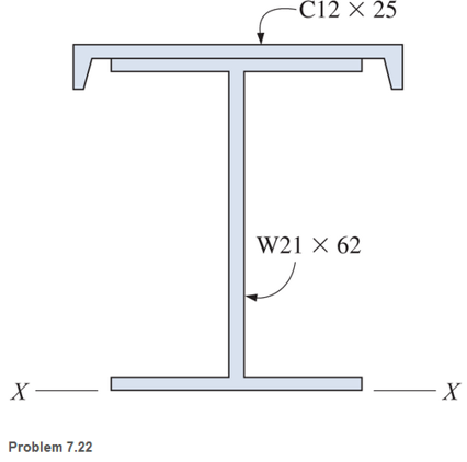
Chapter 7, Problem 7.22SP
A built-up steel member is composed of a
Expert Solution & Answer
Want to see the full answer?
Check out a sample textbook solution
Students have asked these similar questions
Determine the resultant internal loadings acting on the cross section at ‘C’ of the machine shaft shown. The shaft is supported by journal bearings at ‘A’ and ‘B’ which only exert vertical forces on the shaft. Use the right side of point ‘C’ in your solution.
The wing spar ABD of a light plane is made from 2014-T6 aluminum and has a cross-
sectional area of 800 mm², a height of 79 mm, and a moment of inertia about its
neutral axis of 1.07(106) mª. Assume A, B, and C' are pins. The neutral axis passes
through the cross-section at half of its height. Connection is made along the central
longitudinal axis of the spar. The anticipated loading is to be as shown. (Figure 1)
Determine the absolute maximum bending stress in the spar.
0.6 m
14.4 kN/m
0.9 m
B
-1.8 m-
Question 17
A wide flange section has the following properties:
bf = 200 mm
tf = 8 mm
d = 300 mm
tw = 11 mm
Calculate the radius of gyration in mm about the y-axis.
Chapter 7 Solutions
Applied Statics and Strength of Materials (6th Edition)
Ch. 7 - A cylindrical cast-iron casting has an axial bole...Ch. 7 - Locate the center of gravity of the cast-iron...Ch. 7 - A 5-in.-diameter steel sphere is rigidly attached...Ch. 7 - A solid steel shaft is fabricated as shown. Locate...Ch. 7 - A wood mallet has a cylindrical head 6 in. long...Ch. 7 - The built-up member shown is composed of two...Ch. 7 - A concrete member has a cross section as shown....Ch. 7 - A thin steel plate, having the dimensions shown,...Ch. 7 - The U-shaped built-up section shown is composed of...Ch. 7 - Locate the centroid of the area shown. In part...
Ch. 7 - Locate the X-X and Y-Y centroidal axes for the...Ch. 7 - A built-up steel member is composed of a W1871...Ch. 7 - Locate the X-X and Y-Y centroidal axes for the...Ch. 7 - Find the center of gravity for the three-axle...Ch. 7 - For the following computer problems, any...Ch. 7 - For the following computer problems, any...Ch. 7 - For the following computer problems, any...Ch. 7 - A 2.in,-diameler hole, 5 in. long, is drilled into...Ch. 7 - Locate the center of gravity of the cube in...Ch. 7 - The head of a maul is made of steel d is 3 in. in...Ch. 7 - Locate the X-X centroidal axes for the cross...Ch. 7 - A built-up steel member is composed of a W2162...Ch. 7 - Locate the X-X centroidal axes for the cross...Ch. 7 - Locate the X-X and Y-Y centroidal axes for the...Ch. 7 - Locate the X-X and Y-Y centroidal axes for the...Ch. 7 - For the area shown, the X-X centroidal axis is...Ch. 7 - Locate the X-X and Y-Y centroidal axes for the...Ch. 7 - Locate the X-X and Y-Y centroidal axes for the...
Knowledge Booster


Learn more about
Need a deep-dive on the concept behind this application? Look no further. Learn more about this topic, mechanical-engineering and related others by exploring similar questions and additional content below.Similar questions
- Compute the cross product C=AB for each of the cases given in Prob. 1.51 Identify the units of each product.arrow_forward3. The aluminum block has the rectangular cross-section and is subjected to an axial compressive force of 8 kips. The 1.5-in side changed its length to 1.50014 inches. Use E = 10 x 10³ ksi. Calculate the new length of the 2-inch side. Answer: Lnew = 2.00019 in 1.5 in 2 in. 8 kip- 8 kip 3 in. 4. A solid cylinder of diameter D is subjected to an axial load P. Show that its change in diameter is 8D = 4Pv/лDE.arrow_forwardSix 7/8-inch-diameter rivets fasten the plate into the fixed member. Determine the MAXIMUM shearing stress and MINIMUM shearing stress caused in each rivet by the 14 kip loads. (in ksi) Note: Show the illustration and computation of the centroid. 14 kips 3 in. 3 in. 14 kips Figure P-334 P. 10 in.arrow_forward
- Problem 1: The steel pipe has an inner diameter of 2.75 in and an outer diameter of 3 in. The pipe is fixed to the ground at C, and a wrench is attached to the opposite end. The wrench is subjected to a horizontal force of 20 lb that acts in -z direction. Points A and B are located on the surface of the pipe at the same cross section. Note that A lies directly above the -y axis, and B lies directly above the +z axis. 20 lb 10 in. A B X 12 in.. (a) Find the normal and shear stresses at points A and B. (b) Find the principal stresses at points A and B. (c) Show all stresses from parts (a) and (b) on properly oriented elements, relative to the given coordinate system.arrow_forwardThe hollow square cross section shown has a wall thickness, T, of 12.0 mm. Determine the second moment of area of the cross section. Note: Give your answer in mm² Note: Do NOT include units in your answer 100mm Answer: K-Tarrow_forwardA small stepladder has vertical rails and horizontal steps formed from a C-section aluminum channel. Two rivets, one in front and one in back, secure the ends of each step. The rivets attach the steps to the left and right hand rails. A 225 lb person stands in the center of a step. If rivets are formed of 6061-T6 aluminum, what should be the diameter d of the rivets? Use a factor of safety of 8 and round your answer to the nearest 1/16 of an in.arrow_forward
- A W867 section is joined to a C1020 section to form a structural member that has the cross section shown. Calculate Ix and Iy for this cross section. (See Probs. 9.13 and 9.16 for the properties of the structural sections.)arrow_forwardThe plate shown is fastened to the fixed member by five 10-mm-diameter rivets. Compute the value of P so that the average shearing stress in any rivet does not exceed 70 MPa. Note: Show the illustration and computation of the centroid. P. 120 mm 80 mm 40 mm 40 mm 100 mm 80 mm 120 mmarrow_forwardThe two steel shafts (1) and (2) each Ø10 should be connected to each other with the help of the sleeve (3) (Øinner = 10, Øoutside = 15) also made of steel and two rivets at the points shown. The shaft (1) is firmly clamped on the left- hand side, the force F = 100 N acts on shaft 2 in the direction of the arrow. How are the brass round rivets to be dimensioned so that a safety of the coupling against failure of S = 10 is achieved? hole for rivets 1 F 3 a) What type of connection does a riveted connection have? b) What type of load does the rivet have? c) What is the diameter of the rivets? d) Which areas of the rivet are loaded? (Draw in figure and formula) e) Dimension the rivetarrow_forward
- Question 1: Given that Tuitow = 50 MPa for the rod AB and tattow = 25 MPa for the rod BC. If T=1250 N.m, find the required radius for both rods. Ahmtmum AB = BC =arrow_forwardIf the overhanging beam is made of wood having the allowable tensile and compressive stresses of 4Mpa and 5Mpa, determine the maximum concentrated force P that can be applied at the free end. Can you also please explain the calculation of centroid. I'm a bit confused of the values that I need to use. Thank youarrow_forwardThe axial and circumferential stress experienced by the cylinder wall at mid-depth (1m as shown)arrow_forward
arrow_back_ios
SEE MORE QUESTIONS
arrow_forward_ios
Recommended textbooks for you
 International Edition---engineering Mechanics: St...Mechanical EngineeringISBN:9781305501607Author:Andrew Pytel And Jaan KiusalaasPublisher:CENGAGE L
International Edition---engineering Mechanics: St...
Mechanical Engineering
ISBN:9781305501607
Author:Andrew Pytel And Jaan Kiusalaas
Publisher:CENGAGE L
Mechanical Engineering: Centroids & Center of Gravity (1 of 35) What is Center of Gravity?; Author: Michel van Biezen;https://www.youtube.com/watch?v=Tkyk-G1rDQg;License: Standard Youtube License