
INTERNATIONAL EDITION---Engineering Mechanics: Statics, 14th edition (SI unit)
14th Edition
ISBN: 9780133918922
Author: Russell C. Hibbeler
Publisher: PEARSON
expand_more
expand_more
format_list_bulleted
Videos
Textbook Question
Chapter 5.4, Problem 23P
If the roller at A and the pin at B can support a load up to 4 kN and 8 kN, respectively, determine the maximum intensity of the distributed load w, measured in kN/m, so that failure of the supports does not occur.
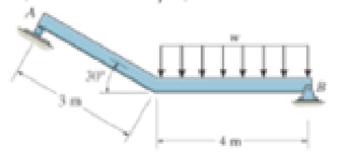
Probs. 5-22/23
Expert Solution & Answer

Learn your wayIncludes step-by-step video

schedule12:01
Students have asked these similar questions
The bracket is held to the wall using three A-36 steel bolts at B, C, and D. Each bolt has a diameter of 0.5 in. and an unstretched length of 2 in. If a force of 800 lb is placed on the bracket as shown,determine the force developed in each bolt. For the calculation, assume that the bolts carry no shear; rather, the vertical force of 800 lb is supported by the toe at A. Also, assume that the wall and bracket are rigid. A greatly exaggerated deformation of the bolts is shown.
The bracket is held to the wall using three A-36 steel bolts at B, C, and D. Each bolt has a diameter of 0.5 in. and an unstretched length of 2 in. If a force of 800 lb is placed on the bracket as shown, determine the force developed in each bolt. For the calculation, assume that the bolts carry no shear; rather, the vertical force of 800 lb is supported by the toe at A. Also, assume that the wall and bracket are rigid. A greatly exaggerated deformation of the bolts is shown.
explain how to find the resultant internal
loading acting on the cross section at point A. Draw all
necessary free-body diagrams and indicate the relevant
equations of equilibrium. Do not calculate values The lettered
dimensions, angles, and loads are assumed to be known.
P7-1.
м
в
-a/2--/2-
Chapter 5 Solutions
INTERNATIONAL EDITION---Engineering Mechanics: Statics, 14th edition (SI unit)
Ch. 5.2 - Draw the free-body diagram for the following...Ch. 5.2 - Draw the free-body diagram for the following...Ch. 5.2 - Draw the free-body diagram for the following...Ch. 5.2 - Draw the free-body diagram for the following...Ch. 5.2 - Draw the free-body diagram for the following...Ch. 5.2 - Draw the free-body diagram for the following...Ch. 5.2 - Draw the free-body diagram for the following...Ch. 5.2 - Draw the free-body diagram for the following...Ch. 5.2 - Draw the free-body diagram for the following...Ch. 5.4 - Draw the free body diagram of each object. Prob....
Ch. 5.4 - Determine the horizontal and vertical components...Ch. 5.4 - Determine the horizontal and vertical components...Ch. 5.4 - The truss is supported by a pin at A and a roller...Ch. 5.4 - Determine the components of reaction at the fixed...Ch. 5.4 - The 25 kg bar has a center of mass at G. If it is...Ch. 5.4 - Determine the reactions at the smooth contact...Ch. 5.4 - Determine the components of the support reactions...Ch. 5.4 - Determine the reactions at the supports. Prob....Ch. 5.4 - Determine the horizontal and vertical components...Ch. 5.4 - Determine the reactions at the supports. Prob....Ch. 5.4 - Determine the reactions at the supports. Prob....Ch. 5.4 - Determine the reactions at the supports. Prob....Ch. 5.4 - Determine the tension in the cable and the...Ch. 5.4 - The man attempts to a up port the toad of boards...Ch. 5.4 - Determine the components of reaction at the...Ch. 5.4 - The man has a weight W and stands at the center of...Ch. 5.4 - A uniform glass rod having a length L is placed in...Ch. 5.4 - The uniform rod AB has a mass of 40 kg. Determine...Ch. 5.4 - If the intensity of the distributed load acting on...Ch. 5.4 - If the roller at A and the pin at B can support a...Ch. 5.4 - The relay regulates voltage and current. Determine...Ch. 5.4 - Determine the reactions on the bent rod which is...Ch. 5.4 - The mobile crane is symmetrically supported by two...Ch. 5.4 - Determine the reactions acting on the smooth...Ch. 5.4 - A linear torsional spring deforms such that an...Ch. 5.4 - Determine the force P needed to pull the 50-kg...Ch. 5.4 - Determine the magnitude and direction of the...Ch. 5.4 - The operation of the fuel pump for an automobile...Ch. 5.4 - Determine the magnitude of force at the pin A and...Ch. 5.4 - The dimensions of a jib crane, which is...Ch. 5.4 - The dimensions of a jib crane, which is...Ch. 5.4 - The smooth pipe rests against the opening at the...Ch. 5.4 - The beam of negligible weight is supported...Ch. 5.4 - The cantilevered jib crane is used to support the...Ch. 5.4 - The cantilevered jib crane is used to support the...Ch. 5.4 - The bar of negligible weight is supported by two...Ch. 5.4 - Determine the stiffness k of each spring so that...Ch. 5.4 - The bulk head AD Is subjected to both water and...Ch. 5.4 - The boom supports the two vertical loads. Neglect...Ch. 5.4 - The boom is intended to support two vertical loads...Ch. 5.4 - The 10-kg uniform rod is pinned at end A. If It is...Ch. 5.4 - If the truck and its contents have a mass of 50 kg...Ch. 5.4 - Three uniform books each having a weight W and...Ch. 5.4 - Determine the reactions at the pin A and the...Ch. 5.4 - If rope BC will fail when the tension becomes 50...Ch. 5.4 - The rigid metal strip of negligible weight is used...Ch. 5.4 - The rigid metal strip of negligible weight is used...Ch. 5.4 - The cantilever footing is used to support a wail...Ch. 5.4 - The uniform beam has a weight Wand length l and is...Ch. 5.4 - A boy stands out at the end of the diving board,...Ch. 5.4 - The 30-N uniform rod has a length of l = 1 m. If s...Ch. 5.4 - The uniform rod has a length I and weight W. It is...Ch. 5.4 - I he uniform rod of length L and weight W is...Ch. 5.4 - Assuming that the foundation exerts a linearly...Ch. 5.4 - Assuming that the foundation exerts a linearly...Ch. 5.4 - If it is also subjected to a couple moment of 100...Ch. 5.4 - Determine the distance d for placement of the load...Ch. 5.4 - If d = 1 m, and = 30, determine me normal...Ch. 5.4 - The man attempts to pull the tour wheeler up the...Ch. 5.4 - Where is the best place to arrange most of the...Ch. 5.7 - Draw the free-body diagram of each object.Ch. 5.7 - In each case, write the moment equations about the...Ch. 5.7 - The uniform plate has a weight of 500 lb....Ch. 5.7 - Determine the reactions at the roller support A,...Ch. 5.7 - The rod is supported by smooth journal bearings at...Ch. 5.7 - Determine the support reactions at the smooth...Ch. 5.7 - Determine the force developed in the short link...Ch. 5.7 - Determine the components of reaction that the...Ch. 5.7 - Determine the tension each rope and the force that...Ch. 5.7 - If these components have weights WA = 45000 Wa =...Ch. 5.7 - Determine the components of reaction at the fixed...Ch. 5.7 - Determine the vertical reactions at the wheels C...Ch. 5.7 - Determine the components of reaction at A, the...Ch. 5.7 - Determine the tension in each of the three...Ch. 5.7 - Determine the components of reaction at hinges A...Ch. 5.7 - Determine me tension in each cable and the...Ch. 5.7 - The cables are attached to a smooth collar ring at...Ch. 5.7 - Determine the components of reaction at the...Ch. 5.7 - Determine the components of reaction at the...Ch. 5.7 - Determine the components of reaction at the...Ch. 5.7 - Determine the magnitude of F which will cause the...Ch. 5.7 - Determine the components of reaction at A and the...Ch. 5.7 - Determine the components of reaction at these...Ch. 5.7 - Determine the components or reaction at these...Ch. 5.7 - Compute the x, y, z components of reaction at the...Ch. 5.7 - Determine the magnitude of F2 which will cause the...Ch. 5.7 - At A the connection is with a ball-and-socket....Ch. 5.7 - If it is supported by a ball-and-socket joint at C...Ch. 5.7 - Determine the x, y, z components of reaction at...Ch. 5.7 - Determine the horizontal tension T in the belt on...Ch. 5.7 - Determine the horizontal tension T in the belt on...Ch. 5.7 - Determine the components of reaction at A and the...Ch. 5.7 - If the roller at 8 can sustain a maximum load of 3...Ch. 5.7 - Determine the reactions at the supports A and B...Ch. 5.7 - Determine the normal reaction at the roller A and...Ch. 5.7 - Determine the horizontal and vertical components...Ch. 5.7 - Determine the x, y, z components of reaction at...Ch. 5.7 - Determine the horizontal equilibrium force P that...Ch. 5.7 - Determine the x, y, z components of reaction at...Ch. 5.7 - Determine the x and z components of reaction at...
Additional Engineering Textbook Solutions
Find more solutions based on key concepts
The assembly consists of two A992 steel bolts AB and EF and an 6061-T6 aluminum rod CD. When the temperature is...
Mechanics of Materials
What parts are included in the vehicle chassis?
Automotive Technology: Principles, Diagnosis, and Service (5th Edition)
In each case, construct the parallelogram law to show FR = F1 + F2. Then establish the triangle rule, where FR ...
Statics and Mechanics of Materials (5th Edition)
For the manometer shown in Fig. 3.30, calculate (pA - Pb) Figure 3.30
Applied Fluid Mechanics (7th Edition)
14. When one tries to stop a car, both the reaction time of the driver and the braking time must be considered....
Thinking Like an Engineer: An Active Learning Approach (4th Edition)
2.12 A telephone pole s braced by a guy wire that exerts a 300-lb pull on the top of the pole, as shown. The g...
Applied Statics and Strength of Materials (6th Edition)
Knowledge Booster


Learn more about
Need a deep-dive on the concept behind this application? Look no further. Learn more about this topic, mechanical-engineering and related others by exploring similar questions and additional content below.Similar questions
- Determine the vertical component of reaction at the pin A to support the steel frame if force F = 41 kN. Supply the answer in kN. F -1 m-1 m- B 30 kN · m 3 m COarrow_forward5-13. Determine the components of the support reac at the fixed support A on the cantilevered beam. 6 kN 30 30 1.5 m 4 kN 1.5 m 1.5 m- Q2arrow_forward7-14. The boom DF of the jib crane and the column DE have a uniform weight of 750 N/m. If the hoist and load weigh 1500 N, determine the resultant internal loadings in the crane on cross sections through points A, B, and C. -24m -0.9 m 1.5 m 06 m 1500 N 2.1 marrow_forward
- 13-50. The C-frame is used in a riveling machine. II the force at the ram on the clamp at Ds P=8 EN, skelch the stres distribution acting over the section a-a. -200 mm 10 pan 60 mm - -10 mmarrow_forwardThe boom DF at the job crane and the column DE have a uniform weight of sw N/m. If the hoist and load weight P N, determine the resultant internal loading in the crane on cross-section through points A, B and C. h2 L1=1 m L2=2 m L3=1 m h1=1 m h2=1.3 m h1 P=540 N Sw=18 N/m D E B L1 L2 A L3 P Farrow_forwardDetermine the magnitude of the pin force at A. Assume W = 900 Ib, a = 5.8 ft, b = 3.9 ft, r = 9 in. B W Answer: A = i Ibarrow_forward
- *4-12. The rigid metal strip of negligible weight is used as part of an electromagnetic switch. If the stiffness of the springs at A and B is k -5 N/m and the strip is originally horizontal when the springs are unstretched, determine the smallest force Fneeded to close the contact gap at C. -50 mm -50 mm 10 mmarrow_forwardexplain how to find the resultant internal loading acting on the cross section at point A. Draw all necessary free-body diagrams, and indicate the relevant equations of equilibrium. Do not calculate values The lettered dimensions, angles, and loads are assumed to be known. P7-1.arrow_forward*3-8. The strut is supported by a pin at C and an A-36 steel guy wire AB. If the wire has 'a diameter of 5 mm, determine how much it stretches when the distributed load acts on the strut. 60 3.4 kN/m 2.7 marrow_forward
- The railcar docklight is supported by the 1/8-in.-diameter pin at A. If the lamp weighs 4.1 lb, and the extension arm AB has a weight of 0.6 lb/ft. 3 ft -1.25 in Part A Determine the average shear stress in the pin needed to support the lamp. Hint:The shear force in the pin is caused by the couple moment required for equilibrium at A. Express your answer to three significant figures and include appropriate units. Value Unitsarrow_forwardThe bracket is held to the wall using three A-36 steel bolts at B, C, and D. Each bolt has a diameter of 0.5 in. and an unstretched length of 2 in. If a force of 800 lb is placed on the bracket as shown, determine how far, s, the top bracket at bolt D moves away from the wall. For the calculation, assume that the bolts carry no shear; rather, the vertical force of 800 lb is supported by the toe at A. Also, assume that the wall and bracket are rigid. A greatly exaggerated deformation of the bolts is shown.arrow_forwardThe 10-mm-diameter bolt is made of an aluminum alloy. It fits through a magnesium sleeve that has an inner diameter of 15 mm and an outer diameter of 25 mm. The original lengths of the bolt and sleeve are 80 mm and 50 mm, respectively. If after the nut on the bolt is tightened the tension in the bolt is 10 kN, determine the change in dimension of the cross-section of the bolt and the sleeve. Assume the material at A is rigid. E = 70 GPa, Emg = 45 GPa, Ga = 26 GPa, Gmg = 17 GPa.arrow_forward
arrow_back_ios
SEE MORE QUESTIONS
arrow_forward_ios
Recommended textbooks for you
 Elements Of ElectromagneticsMechanical EngineeringISBN:9780190698614Author:Sadiku, Matthew N. O.Publisher:Oxford University Press
 Mechanics of Materials (10th Edition)Mechanical EngineeringISBN:9780134319650Author:Russell C. HibbelerPublisher:PEARSON
 Thermodynamics: An Engineering ApproachMechanical EngineeringISBN:9781259822674Author:Yunus A. Cengel Dr., Michael A. BolesPublisher:McGraw-Hill Education
 Control Systems EngineeringMechanical EngineeringISBN:9781118170519Author:Norman S. NisePublisher:WILEY
 Mechanics of Materials (MindTap Course List)Mechanical EngineeringISBN:9781337093347Author:Barry J. Goodno, James M. GerePublisher:Cengage Learning
 Engineering Mechanics: StaticsMechanical EngineeringISBN:9781118807330Author:James L. Meriam, L. G. Kraige, J. N. BoltonPublisher:WILEY
Elements Of Electromagnetics
Mechanical Engineering
ISBN:9780190698614
Author:Sadiku, Matthew N. O.
Publisher:Oxford University Press
Mechanics of Materials (10th Edition)
Mechanical Engineering
ISBN:9780134319650
Author:Russell C. Hibbeler
Publisher:PEARSON
Thermodynamics: An Engineering Approach
Mechanical Engineering
ISBN:9781259822674
Author:Yunus A. Cengel Dr., Michael A. Boles
Publisher:McGraw-Hill Education
Control Systems Engineering
Mechanical Engineering
ISBN:9781118170519
Author:Norman S. Nise
Publisher:WILEY
Mechanics of Materials (MindTap Course List)
Mechanical Engineering
ISBN:9781337093347
Author:Barry J. Goodno, James M. Gere
Publisher:Cengage Learning
Engineering Mechanics: Statics
Mechanical Engineering
ISBN:9781118807330
Author:James L. Meriam, L. G. Kraige, J. N. Bolton
Publisher:WILEY
Mechanical SPRING DESIGN Strategy and Restrictions in Under 15 Minutes!; Author: Less Boring Lectures;https://www.youtube.com/watch?v=dsWQrzfQt3s;License: Standard Youtube License