
Mechanics of Materials (10th Edition)
10th Edition
ISBN: 9780134319650
Author: Russell C. Hibbeler
Publisher: PEARSON
expand_more
expand_more
format_list_bulleted
Concept explainers
Videos
Textbook Question
Chapter 3.7, Problem 3.25P
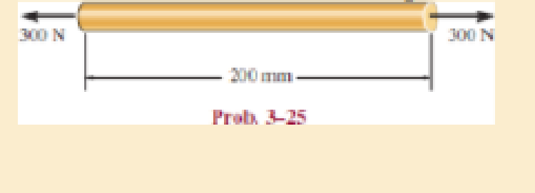
The acrylic plastic rod is 200 mm long and 15 mm in diameter. If an axial load of 300 N is applied to it, determine the change in its length and the change in its diameter. Ep = 2.70 GPa, vp = 0.4
Expert Solution & Answer
Want to see the full answer?
Check out a sample textbook solution
Students have asked these similar questions
1. The acrylic plastic rod is 200 mm long and 15 mm in
diameter. If an axial load of 300 N is applied to it, determine
the change in its length and the change in its diameter.
Material parameters are Ep = 2.70 GPa and vp = 0.4.
300 N
200 mm
300 N
The acrylic plastic rod is 200 mm long and
15 mm in diameter. If an axial load of 300
N is applied to it, what is the change in its
diameter? E, = 2.70 GPa, v, = 0.5.
300 N
300 N
200 mm
Select one:
a. -4.72 µm
O b. -6.29 µm
C. -3.77 µm
d. 3.77 µm
е. 4.72 um
O f. None
The acrylic plastic rod is 200 mm long and 15 mm in diameter. If an axial load of 300 N is applied to it, determine the change in its length and the change in its diameter. Ep = 2.70 GPa, np = 0.4.
Chapter 3 Solutions
Mechanics of Materials (10th Edition)
Ch. 3.4 - Define a homogeneous material.Ch. 3.4 - Indicate the points on the stress-strain diagram...Ch. 3.4 - Define the modulus of elasticity E.Ch. 3.4 - At room temperature, mild steel is a ductile...Ch. 3.4 - Engineering stress and strain are calculated using...Ch. 3.4 - As the temperature increases the modulus of...Ch. 3.4 - A 100-mm-long rod has a diameter of 15 mm. If an...Ch. 3.4 - A bar has a length of 8 in. and cross-sectional...Ch. 3.4 - A 10-mm-diameter rod has a modulus of elasticity...Ch. 3.4 - The material for the 50-mm-long specimen has the...
Ch. 3.4 - The material for the 50-mm-long specimen has the...Ch. 3.4 - If the elongation of wire BC is 0.2 mm after the...Ch. 3.4 - A tension test was performed on a steel specimen...Ch. 3.4 - Data taken from a stress-strain test for a ceramic...Ch. 3.4 - Data taken from a stress-strain test for a ceramic...Ch. 3.4 - The stress-strain diagram for a steel alloy having...Ch. 3.4 - The stress-strain diagram for a steel alloy having...Ch. 3.4 - The stress-strain diagram for a steel alloy having...Ch. 3.4 - The rigid beam is supported by a pin at C and an...Ch. 3.4 - The rigid beam is supported by a pin at C and an...Ch. 3.4 - Acetal plastic has a stress-strain diagram as...Ch. 3.4 - The stress-strain diagram for an aluminum alloy...Ch. 3.4 - The stress-strain diagram for an aluminum alloy...Ch. 3.4 - The stress-strain diagram for an aluminum alloy...Ch. 3.4 - A bar having a length of 5 in. and cross-sectional...Ch. 3.4 - The rigid pipe is supported by a pin at A and an...Ch. 3.4 - The rigid pipe is supported by a pin at A and an...Ch. 3.4 - Direct tension indicators are sometimes used...Ch. 3.4 - The rigid beam is supported by a pin at C and an...Ch. 3.4 - The rigid beam is supported by a pin at C and an...Ch. 3.4 - The stress-strain diagram for a bone is shown, and...Ch. 3.4 - The stress-strain diagram for a bone is shown and...Ch. 3.4 - The two bars are made of a material that has the...Ch. 3.4 - The two bars are made of a material that has the...Ch. 3.4 - The pole is supported by a pin at C and an A-36...Ch. 3.4 - The bar DA is rigid and is originally held in the...Ch. 3.7 - A 100-mm-long rod has a diameter of 15 mm. If an...Ch. 3.7 - A solid circular rod that is 600 mm long and 20 mm...Ch. 3.7 - A 20-mm-wide block is firmly bonded to rigid...Ch. 3.7 - A 20-mm-wide block is bonded to rigid plates at...Ch. 3.7 - The acrylic plastic rod is 200 mm long and 15 mm...Ch. 3.7 - The plug has a diameter of 30 mm and fits within a...Ch. 3.7 - The elastic portion of the stress-strain diagram...Ch. 3.7 - The elastic portion of the stress-strain diagram...Ch. 3.7 - The brake pads for a bicycle tire are made of...Ch. 3.7 - The lap joint is connected together using a 1.25...Ch. 3.7 - The lap joint is connected together using a 1.25...Ch. 3.7 - The rubber block is subjected to an elongation of...Ch. 3.7 - The shear stress-strain diagram for an alloy is...Ch. 3.7 - A shear spring is made from two blocks of rubber,...Ch. 3 - The elastic portion of the tension stress-strain...Ch. 3 - The elastic portion of the tension stress-strain...Ch. 3 - The rigid beam rests in the horizontal position on...Ch. 3 - The wires each have a diameter of 12 in., length...Ch. 3 - The wires each have a diameter of 12 in., length...Ch. 3 - diameter steel bolts. If the clamping force in...Ch. 3 - The stress-strain diagram for polyethylene, which...Ch. 3 - The pipe with two rigid caps attached to its ends...Ch. 3 - The 8-mm-diameter bolt is made of an aluminum...Ch. 3 - An acetal polymer block is fixed to the rigid...
Additional Engineering Textbook Solutions
Find more solutions based on key concepts
The magnitude of vector force F (F) and its direction θ.
Engineering Mechanics: Statics & Dynamics (14th Edition)
The spring has a stiffness k = 200 N/m and is unstretched when the 25-kg block is at A. Determine the accelerat...
Engineering Mechanics: Dynamics (14th Edition)
What parts are included in the vehicle chassis?
Automotive Technology: Principles, Diagnosis, and Service (5th Edition)
Comprehension Check 7-1
Express the following values using an appropriate Sl prefix such that there are only on...
Thinking Like an Engineer: An Active Learning Approach (3rd Edition)
Determine the force in members BC, CF, and FE and state if the members are in tension or compression. Prob. F5-...
Statics and Mechanics of Materials (5th Edition)
What parts are included in the vehicle chassis?
Automotive Technology: Principles, Diagnosis, And Service (6th Edition) (halderman Automotive Series)
Knowledge Booster


Learn more about
Need a deep-dive on the concept behind this application? Look no further. Learn more about this topic, mechanical-engineering and related others by exploring similar questions and additional content below.Similar questions
- A plastic rod is 200mm long and 15mm in diameter. If a tensile load of 300N is applied to it, determine the change in its length and the change in its diameter. Assume Modulus of elasticity (E) = 2.70 GPa, and poisson's ratio (v) = 0.4. indicate free body diagramarrow_forwardA uniform edge load of 500 lb>in. and 350 lb>in. is applied to the polystyrene specimen. If the specimen is originally square and has dimensions of a = 2 in., b = 2 in., and a thickness of t = 0.25 in., determine its new dimensions a , b , and t after the load is applied. Ep = 597(103) psi andnp = 0.25.arrow_forwardIn the graft, the 6-meter-high arm is manufactured using the l profile given below. It is fixed to both ends of the arm with a built-in support. If the yield strength of the material is σy=400 MPa Elasticity modulus E=2*105 MPa If the safety factor used in the design is 2.5, the arm in question is What is the highest axial load it can safely carry?arrow_forward
- Need asap A round brass rod 30 mm in diameter and 200 mm long is subjected to a compressive force of 100 kN. If μ = 0.33 and E = 105 GPa. Determine the change in diameter. In mm. Thanksarrow_forwardQuestion 1 A tensile load of 40 kN is acting on a rod of diameter 40 mm and of length 4 m. A bore of diameter 20 mm is made centrally on the rod. To what length the rod should be bored so that the total extension will increase 30% under the same tensile load. Take E = 2 x 10$ N/mm2.arrow_forwardA copper bar consists from three sections: sections 1 is of 25 mm diameter and 60 mm long, section 2 is of 15 mm diameter and 50 mm long and section 3 is 20 mm square and 40 mm long. The bar is subjected to an axial tensile load which induces a stress of 20 MN/m2 on the smallest cross section. Determine the total Increase in the length of the bar when the load is applied. For copper E=100 GN/m2.arrow_forward
- A bar made of a space age polymer has the stress-strain curve shown below. If the bar has a length of 2 ft and a cross section area of 0.925 in², and an axial load of 2 kip is applied, what is its elongation? The equation of the stress-strain curve is: o = o (psi) The elongation,8 = in. 96000.28 + ε (in/inarrow_forwardA uniform edge load of w1 = 530 lb/in. and w2 = 320 lb/in. is applied to the polystyrene specimen. Ep = 597(103)psi and νp = 0.25. 1) Part A: If the specimen is originally square and has dimensions of a = 1 in ., b = 2 in., and a thickness of t = 0.35 in. , determine its new dimension a′ after the load is applied. 2) Part B: Determine its new dimension b′ after the load is applied. 3) Part C: Determine its new dimension t′ after the load is applied.arrow_forward2. A circular steel bar with with a diameter of 3 in and length of 2 m is subjected to an tensile force of 80 kN. Determine the change in length and the change in its cross section if the material behaves elastically. Let y be the longitudinal axis and Modulus of Elasticity be 200 GPa. Assume v=0.32arrow_forward
- 3. The aluminum block has the rectangular cross-section and is subjected to an axial compressive force of 8 kips. The 1.5-in side changed its length to 1.50014 inches. Use E = 10 x 10³ ksi. Calculate the new length of the 2-inch side. Answer: Lnew = 2.00019 in 1.5 in 2 in. 8 kip- 8 kip 3 in. 4. A solid cylinder of diameter D is subjected to an axial load P. Show that its change in diameter is 8D = 4Pv/лDE.arrow_forwardThe copper bar is subjected to a uniform loading shown in Fig. 10–24. Ifit has a length a = 300 mm, width b = 50 mm, and thickness t = 20 mmbefore the load is applied, determine its new length, width, and thicknessafter application of the load. Take Ecu = 120 GPa, ncu = 0.34.arrow_forwardThe timber member has a cross-sectional area of 1750 mm? and its modulus of elasticity is 12 GPa. Compute the change in the total length of the member after the loads shown in Figure 7 are applied. 25KH 20 KN 3akN 1.5m 3 marrow_forward
arrow_back_ios
SEE MORE QUESTIONS
arrow_forward_ios
Recommended textbooks for you
 Elements Of ElectromagneticsMechanical EngineeringISBN:9780190698614Author:Sadiku, Matthew N. O.Publisher:Oxford University Press
 Mechanics of Materials (10th Edition)Mechanical EngineeringISBN:9780134319650Author:Russell C. HibbelerPublisher:PEARSON
 Thermodynamics: An Engineering ApproachMechanical EngineeringISBN:9781259822674Author:Yunus A. Cengel Dr., Michael A. BolesPublisher:McGraw-Hill Education
 Control Systems EngineeringMechanical EngineeringISBN:9781118170519Author:Norman S. NisePublisher:WILEY
 Mechanics of Materials (MindTap Course List)Mechanical EngineeringISBN:9781337093347Author:Barry J. Goodno, James M. GerePublisher:Cengage Learning
 Engineering Mechanics: StaticsMechanical EngineeringISBN:9781118807330Author:James L. Meriam, L. G. Kraige, J. N. BoltonPublisher:WILEY
Elements Of Electromagnetics
Mechanical Engineering
ISBN:9780190698614
Author:Sadiku, Matthew N. O.
Publisher:Oxford University Press
Mechanics of Materials (10th Edition)
Mechanical Engineering
ISBN:9780134319650
Author:Russell C. Hibbeler
Publisher:PEARSON
Thermodynamics: An Engineering Approach
Mechanical Engineering
ISBN:9781259822674
Author:Yunus A. Cengel Dr., Michael A. Boles
Publisher:McGraw-Hill Education
Control Systems Engineering
Mechanical Engineering
ISBN:9781118170519
Author:Norman S. Nise
Publisher:WILEY
Mechanics of Materials (MindTap Course List)
Mechanical Engineering
ISBN:9781337093347
Author:Barry J. Goodno, James M. Gere
Publisher:Cengage Learning
Engineering Mechanics: Statics
Mechanical Engineering
ISBN:9781118807330
Author:James L. Meriam, L. G. Kraige, J. N. Bolton
Publisher:WILEY
EVERYTHING on Axial Loading Normal Stress in 10 MINUTES - Mechanics of Materials; Author: Less Boring Lectures;https://www.youtube.com/watch?v=jQ-fNqZWrNg;License: Standard YouTube License, CC-BY